Command Center Setup
Advanced Metering Infrastructure (AMI) systems enable powerful grid management capabilities. In addition to sending and receiving meter data, advanced metering and smart grid networks provide remote control and automation of certain distribution system functions to assist utilities with load management, reporting and responding to power outages and monitoring power quality. Ensuring the security of such a system is a top priority.
Because of the current state of the industry and various technologies being deployed, there are no existing uniform security standards for AMI systems. Landis+Gyr is monitoring and participating in the security standards development process currently being conducted by such groups as the AMI Security Task Force (AMI SEC), UtiliSec Advanced Security Acceleration Project (ASAP SG), and the NIST Cybersecurity Coordination Task Group.
The chief concern is ensuring system and network availability while meeting three critical security objectives: Confidentiality, Authentication, and Integrity. By focusing on these objectives, Landis+Gyr is able to effectively manage security risk, while offering a tiered structure of security features to meet the needs of individual utilities.
NOTE: For information on security settings see Landis+Gyr Security Administrators Guide, publication number 98-1035.
Command Center is a secure application that requires users to have unique credentials to log into the software. During the Command Center software installation, one user, with security privileges, is created. This user will be the only person with initial access to the software.
Following is the procedure for logging into Command Center
1.Open an Internet Explorer browser.
2.Enter the assigned Internet address (URL) in the browser’s address bar. The Command Center User Login window will be displayed.
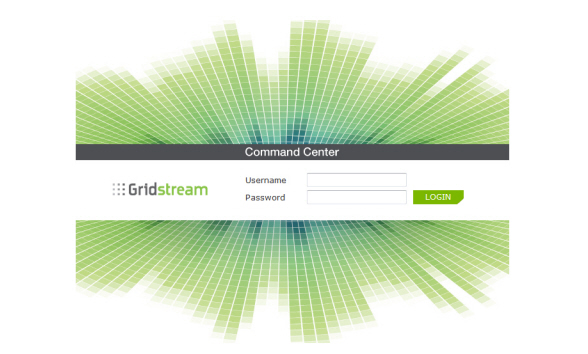
Figure 3 - 1. Command Center User Login Window
3.Type your provided User Name and Password into the spaces provided. The password is case sensitive.
NOTE: After logging in, the user name can be changed by the Administrator and the user can change his/her own password.Passwords are case sensitive and must contain a minimum of 6 characters that consist of at least 1 upper case, 1 lower case and 1 non-alphanumeric character, as well as 1 digit.
4.Click the Login button. The Command Center Message Center tab Home window will be displayed.
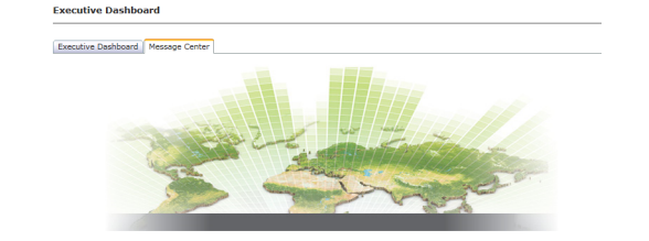
Figure 3 - 2. Command Center Message Center Home Page
The purpose of the Message Center is to display Landis+Gyr generated messages, such as new versions of Command Center, or new feature availability. At the bottom of the window, historical log-in information is displayed.
Navigation in Command Center is similar to navigating an Internet web site. Menu tabs and quick select icons allow for ease of navigation.
Menu options are available for easy access to different functions within Command Center. Each tab will provide a drop down list of sub menu options.
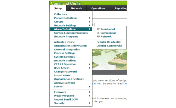
Figure 3 - 3. Command Center Menu Structure
NOTE: The Organization Information setting Menu allows the utility to change the menu layout. The default RF Mesh Command Center layout is MDM.
Quick Select icons, which facilitate navigation, are available in the upper right hand corner. The function of each icon is described in Table 3 - 1.
|
|
Real Time Outage Map: Provides a quick and easy way to review outages in real time on the interactive map interface. |

|
AMI Dashboard: Designed to give the AMI administrator an overview of the AMI devices in the system and ‘bubble up’ any areas of concern. |
|
|
Security Dashboard: The security dashboard is designed to be used on a daily basis to display security related information. |
|
|
Executive Dashboard: Provides an executive level viewpoint of usage statistics and key power quality indicators. |
|
|
System Map: The System Map provides a graphical overview of the mesh deployment superimposed over a map of the area. |
|
|
Home: Navigates to the Command Center Message Center |
|
|
System Dashboard: Provides a view of the entire system, including servers |
|
|
Logout: Allows the user to log out of the Command Center system. |
Upon installation of Command Center, the available menu options are limited to Activate License and Organization Information settings. The Security Administrator must activate the license to unlock the Command Center functionality necessary to manage the utility’s RF Mesh solution. Once the license has been activated, additional utility specific settings must be established.
The Landis+Gyr licensing program allows customers to purchase additional functionality. A software product license grants you the legal right to run or access a software program. A license agreement governs your use of the licensed software program.
With Landis+Gyr licensing programs, staying current gives your business a technological edge to better respond to customer demands and competitive challenges.
There are three steps required to purchase a software license after you have determined which software program(s) you need:
•Determine the license(s) you need.
•Contact your Landis+Gyr sales representative to purchase the product license key.
•Install the license key in Command Center
1.Click Setup > Activate License.
The Activate License window will be displayed.
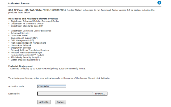
Figure 3 - 4. Activate License
NOTE: If expected menu options are not available, it is likely the license has not been purchased or has not been activated.
A list of currently licensed software is displayed.
2.To activate additional software, enter the Activation code provided by Landis+Gyr Sales in the text box.
...or...
Click the Browse button to navigate to the location of the license file supplied to you by Landis+Gyr.
3.Double-click the license file name to add the file name to the license file text box.
4.Click the Activate button to activate the license file or activation code.
Organization Information Settings
The Organization Information settings allow for the establishment of information related to the top-most level of organization structure. Several Organization Information settings must be configured upon initial installation of the software.
1.Click Setup > Organization Information.
The Organization Information window will be displayed. Settings displayed will vary based on license activation.
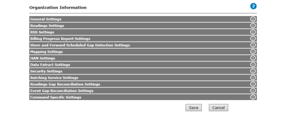
Figure 3 - 5. Organization Information Window
2.Complete the setup described in the following sections:
•General Settings. See “General Settings” on page 28.
•Readings Settings. See “Readings Settings” on page 31.
•RSS Settings. See“RSS Settings” on page 32.
•Billing Progress Report Settings. See “Billing Progress Report Settings” on page 32.
•Store and Forward Scheduled Gap Detection. See “Store and Forward Scheduled Gap Detection Settings” on page 32.
•Mapping Settings. See “Mapping Settings” on page 33.
•HAN Settings. See “HAN Settings” on page 33.
•Data Extract Settings. See “Data Extract Settings” on page 33.
•Security Settings. See “Security Settings” on page 35.
•Batching Service Settings. See “Batching Service Settings” on page 36.
•Readings Gap Reconciliation Settings. See “Readings Gap Reconciliation Settings” on page 37.
•Event Gap Reconciliation Settings. See See “Event Gap Reconciliation Settings” on page 38.
•Command Specific Settings. See “Command Specific Settings” on page 39.
3.When setup is completed click the Save button.
|
Name |
Description |
|---|---|
|
Organization Name |
The organization name is populated from the license file. The organization name cannot be edited. The organization name can only be changed by the Landis+Gyr Sales department if you obtain a new license file. |
|
Organization ID |
Organization ID is an auto-generated value assigned to the organization when the data is inserted into the database. |
|
Owner ID* |
The Owner ID associated with the organization. Must be an integer value between 0 and 16383. NOTE: Changing this value once set, will result in any already deployed endpoints unable to hear commands and start logging bad packets after a period of time. |
|
Time Zone* |
Displays the time zone where the organization is located. |
|
Gridstream Network Id* |
The ID of the Gridstream RF Network. |
|
Zip Code |
Enter your utility’s zip code. The postal zip code is used to retrieve weather related data for the servicing territory of the utility. This temperature data will be displayed along with the customer’s kWh usage on the Service History Report. |
|
Organization Secondary Identifier |
Select the Organization Secondary Identifier from the drop-down list. The organization secondary identifier is the default identifier selected for an organization that will be shown on reports along with the meter number. |
|
Organization Tertiary Identifier |
Select the Organization Tertiary Identifier from the drop-down list. The organization tertiary identifier is the default identifier selected for an organization that will be shown on reports along with the meter number. |
|
Location Level 1 Name |
Enter the name of the organization location at level 1. The default is name is Region. |
|
Location Level 2 Name |
Enter the name of the organization location at level 2. The default is name is District. |
|
Location Level 3 Name |
Enter the name of the organization location at level 3. The default is name is Office. |
|
Menu |
Choose the style used for the main Command Center menu. |
|
Base Installation Directory |
This directory will be used for generating files when a directory is not specified in the file path. |
|
Default FOCUS AX Configuration |
Default FOCUS AX Configuration group used for initial FOCUS AX endpoint configuration. Select the required group from the menu. |
|
kV2c Meter Security Code |
Enter the 3PH Meter Security Code for your location. These codes are programmed into meter memory and act as a “password” to strictly control the communications to meters via OPTOCOM and modem. |
|
S4 Meter Security Code |
These codes are programmed into meter memory and act as a “password” to strictly control the communications to meters via OPTOCOM and modem. |
|
Enhanced Elster A3 Security Code |
These codes are programmed into meter memory and strictly control the communication to meters via OPTOCOM and modem. |
|
Web Service URL* |
The location of the web service on a web server. |
|
Meter Display Alert Threshold |
Displays the number of days beyond which a meter display alert would be issued. The default is 3 days. |
|
Dashboard Refresh Interval |
Select the rate at which the Command Center Dashboard would check to see if it needs to be refreshed. The default value is 1 minute. |
|
Water Units* |
Select the unit of measurement for water usage. Available options are Gallons, Centrum Cubic Feet, Cubic Meters, Cubic Feet. The selected unit of measurement will be displayed in the Data Extract Setup extract items. It will also be the unit of measurement in all relevant reports: Endpoint Data Extract Report, Daily Reads Status Report and the Service History Report. |
|
Gas Units* |
Select the unit of measurement for gas usage. Available options are Cubic Feet, Cubic Meters. |
|
Residential Gas High Flow Alarm Window* |
If the High Flow Alarm feature is enabled for a Residential Gas module, it will raise a warning or alarm if the gas meter's pulse count consistently exceeds the thresholds during this time span. Changing this setting will be applicable for all Residential Gas modules reconfigured by Command Center going forward; Gas modules in Normal state will NOT be automatically reconfigured. |
|
Commercial Gas High Flow Alarm Window* |
If the High Flow Alarm feature is enabled for a Commercial Gas module, it will raise a warning or alarm if the gas meter's pulse count consistently exceeds the thresholds during this time span. Changing this setting will be applicable for all Commercial Gas modules reconfigured by Command Center going forward; Gas modules in Normal state will NOT be automatically reconfigured. |
|
Collector Time Sync Adjustment Threshold |
The number of seconds beyond which a time sync adjustment alert would be triggered on the Dashboard. The default is 10 seconds. |
|
Collector Low Battery Threshold |
The voltage below which a Low Battery Alert will be issued for collectors. |
|
External User Authentication (Security Administrator Only) |
Enables authentication of users using their external (Windows) username and password when checked. |
|
Default AMR Password |
The default AMR password stored in the meters. |
|
Deployment Statistics Rollup Days |
The number of days back from today the Deployment Statistics Report will process. The default is 7 days. |
|
Max Discovered Collectors |
The maximum number of collectors that can be in a Discovered status at one time. (Lowering this setting will not affect Collectors already in a Discovered status.) |
|
Use WAN Addresses |
Select this setting to allow Command Center to assign WAN addresses to Meters/endpoints when latitude/longitude data is available. This setting must be selected in order to enable Geo-coded routing. |
|
Update WAN address when Lat/Long value received |
Select this to make Command Center update WAN addresses when a new Lat/Long GPS coordinate are received for a meter/endpoint. This setting must be selected in order to enable Geo-coded routing. |
|
Maximum number of LAN hops |
The maximum number of LAN addresses a message will use before failing. The default setting is 40 hops. |
|
Maximum number of rows per page |
The maximum number of rows that will be displayed on a window. |
|
Show Meter Alarms on Dashboard |
Displays the meter alarms nugget on the AMI dashboard when checked. |
|
Show Outage Alarms on Dashboard |
Displays the outage alarms nugget on the AMI dashboard when checked. |
|
Enable GSIS |
Enables GSIS when checked. |
|
Enable Ignore ST25 Table |
Enables ignoring of ST25 Table when checked. |
|
Enable MAS/EAS downstream frequency programming |
Enables MAS/EAS downstream frequency programming when checked. |
|
Maximum number of rows returned by Advanced Search |
The maximum number of rows that will be displayed in the search results of the Advanced Search. |
|
Load Side Voltage Threshold on Disconnected Meters |
The voltage above which an unexpected load side voltage event will be reported. The default setting is 40%. |
|
Command Timeout Threshold |
The amount of time to wait (in minutes) for a command response before invoking timeout business logic. |
|
LP Request Days |
Number of Days (between 1 to 44) for which LP could be requested. |
|
Show Collector Communication Module Status |
Indicates whether collector communication module status is visible on collector screen. |
|
Event Extracts: Date/Time Format |
Configures all date/timestamp fields in the Event Extracts to output as the format specifier. Leave Blank for default (Example: 10152014045529PM) formatting. |
|
Show Calculated Net kWh |
Shows the dial reads for the Calculated Net kWh on the Endpoint Information Window, for FOCUS AX and S4x meters Only. |
|
Enable update of KYZ settings during meter reprogramming |
Enables update of KYZ settings when electric meter is reprogrammed using the Meter Program Download command. |
|
Enable update of Service Limiting settings during meter reprogramming |
Enables update of Service Limiting settings when electric meter is reprogrammed using the Meter Program Download command. |
|
Enable Multiple Sets |
Enable Multiple Set support on Endpoint Configuration Group screen. Default value is No. If enabled, enter Maximum Number of Sets. This is the maximum number of sets to be displayed on the reconfiguration screen. Min value is 2, Max value is 16. An error message will be displayed if the value is out of range. |
|
Maximum Number of Sets |
This field is displayed if Enable Multiple Sets is enabled.This is the maximum number of sets to be displayed on the reconfiguration screen. Min value is 2, Max value is 16. An error message will be displayed if the value is out of range. |
|
Retain Lat/Long when Removing Endpoint from Service |
When checked, enables endpoint to retain Latitude/Longitude when removing the endpoint from service. |
|
Filter Smart Meter Past Reads |
Indicates whether the past interval reads from Smart Meter will be discarded. This will be unselected by default. |
|
Lookback period for filtering past reads. |
The number of days beyond which the interval reads from smart meter will be discarded if Filter Smart Meter Past Reads is selected. |
|
Single Event Reporting Selection |
Enables the suppression of Standard Table 3 flags when there are corresponding meter events. The default setting is disabled. |
|
Maximum Latency Commands |
The maximum latency commands value that will be displayed on a screen. |
|
Water Module Default Interval Length |
The default interval length of Series 5 Water modules. |
|
Gas Lost Communication Threshold |
The number of days after which Gas modules that are not communicating with Command Center will be set to status 'Lost Communication'. |
|
* Indicates a required field. |
|
|
Setting |
Description |
|---|---|
|
Validation Group |
Indicates which group will be used to hold the default processing rules for all meters that are not assigned to another Validation Group. |
|
Enable Gas Meters Raw Pulse Count Recording |
Enable to record gas meter raw pulse counts. |
|
RF Gas Meter Default Billing Start Time |
This is the Billing Start Time / Self Read Time for Residential and Commercial Gas modules assigned to default Endpoint Configuration Groups. Changing this setting will be applicable for all Gas modules registering in Command Center going forward; Gas modules in Normal state will NOT be automatically reconfigured. The value also defines the default of the Billing Start Time field on the Residential and Commercial Configuration Groups screen when a new custom Endpoint Configuration Group is created. The value can be modified when creating the custom group. |
|
RF Water Meter Default Billing Start Time |
This is the Billing Start Time for Water modules assigned to default Endpoint Configuration Groups. Changing this setting will be applicable for all Water modules registering in Command Center going forward; Water modules in Normal state will NOT be automatically reconfigured. The value also defines the default of the Billing Start Time field on the Water Configuration Groups screen when a new custom Endpoint Configuration Group is created. The value can be modified when creating the custom group. |
|
Max Interval Data Range Request Minutes |
The maximum number of minutes allowed when issuing 'Get Load Profile' command. |
|
Water Meter Right Sizing Duration |
This is the number of minutes for Right Sizing to collect data from the water meter. The default value is 180 minutes. When a new duration period is entered, Command Center will validate the values. |
|
Setting |
Description |
|---|---|
|
Enable Arming |
Check this flag if Command Center should handle meter service connects by sending arming commands as opposed to immediate remote connect commands. |
|
Setting |
Description |
|---|---|
|
Billing Progress lookback period |
The Billing Progress report looks back for this time period to find billable readings. 3 days is the default. To change the time period, enter the desired number in the number text box and select either days or months from the drop-down list. |
|
Setting |
Description |
|---|---|
|
Start Date Time |
The Start Date Time (local time) for which gaps will not be created by the Gap Collection Process. Changing this date during or after the gap detection process has executed may result in duplicate gap records. |
|
End Date Time |
The End Date Time (local time) for which gaps will not be created by the Gap Collection Process. Changing this date during or after the gap detection process has executed may result in duplicate gap records. |
|
Max Number of Parallel Threads |
The maximum number of parallel threads for scheduled gap detection. |
|
Max Number of Parallel Threads for HV |
The maximum number of parallel threads for scheduled gap detection. |
|
Request Delay Minutes Range |
The number of minutes that are added to the current UTC time to get the next request time. The number is randomly selected within this range. |
|
Scheduled Gap Detection Algorithm |
This setting controls the algorithm that will be used in the back-end processing of the scheduled gap detection. When querying the repository for the given time period and meter batch id, Get Gaps will retrieve only records with gaps. Get All Reads will retrieve all records and then process the records to find gaps. Please consult the system administrator before changing this setting. |
|
Schedule Gap Detection Algorithm for HV |
This setting controls the algorithm that will be used in the back-end processing of the scheduled gap detection. When querying the repository for the given time period and meter batch id, Get Gaps will retrieve only records with gaps. Get All Reads will retrieve all records and then process the records to find gaps. Please consult the system administrator before changing this setting. |
NOTE: Internet access is required to use the mapping features within Command Center.
|
Setting |
Description |
|---|---|
|
Default Zoom Level |
Default zoom level for the system surveyor. |
|
Zoom Level for endpoint display |
The zoom level at which endpoints start being plotted on the map. |
|
Neighboring endpoints maximum distance |
The maximum distance to be used when identifying an endpoint as being another's neighbor. This value will be evaluated as feet, 200 feet is about 1/8 of a mile and 2000 feet is a little less than 1/2 mile. The value must be between 200 and 2000 feet. |
|
Default Latitude |
The default latitude for the system surveyor. |
|
Default Longitude |
The default longitude for the system surveyor. |
|
Real time Outage Tracker Map Refresh Interval |
The refresh interval in milliseconds for real time outage tracker map. The default is set at 120000 milliseconds (2 minutes). |
|
Setting |
Description |
|---|---|
|
HAN Device Registration Days |
Select the number of days the registration window remains open when registering a HAN device. If the consumer fails to join within the established number of days, the device must be deleted from Command Center; then re-registered. Valid values are 1 - 30. |
|
HAN Message Max Length |
The maximum number of characters that can be sent in a message to a HAN device. Valid Values are 1-80. The default is 25. |
|
Heating Cooling Temp Offset Unit |
Select the heating or cooling temperature offset unit from the menu. |
|
Setting |
Description |
|---|---|
|
Manual Entry of Item IDs |
When enabled, extract item IDs can be entered manually on the Data Extract Setup window. |
|
Integer Energy Values |
If checked, only the integer portion of energy values (kWh, kVAh, etc.) is extracted. Uncheck this box to preserve the decimal portion. |
|
Decimal Rounding |
If checked, extracting fewer right-of-decimal digits than available will have no effect on those remaining; excess digits will simply be dropped. If unchecked, the remaining digits will be rounded away from zero. |
|
Incremental Interval Extract File Name Prefix |
Enter the desired prefix for the Interval Extract File. |
|
Incremental Periodic Extract File Name Prefix |
User defined file name prefix for incremental periodic reads extract files. (Gas Only) |
|
Incremental Extract Directory |
Enter the complete path to the folder in which the extract output should be written. |
|
Incremental Interval Extract File Name Suffix |
Indicates the timestamp suffix that will be appended to the file name for uniqueness. |
|
Incremental Interval Extract Format. |
Select the desired format for the Incremental Extract from the following options: |
|
Interval Extracts: Show Time as |
Configures all date/timestamp fields in the incremental Interval Extracts and once-a-day Interval Extracts to be output as local time or UTC time. |
|
Daily Reads Extracts: Show Time as |
Configures all date/timestamp fields in the incremental Daily Reads Extracts and once-a-day Daily Reads Extracts to be output as local time or UTC time. |
|
Max Meters per File for IEC 61968 CIM 2nd Edition Extract. |
The maximum number of meters to include per IEC 61968 CIM 2nd edition extract file. |
|
Max Records per File for IEC 61968 CIM 2nd Edition Extract (0 is unlimited). |
The maximum number of records to include per IEC 61968 CIM 2nd edition extract file. |
|
Device Configuration Extract Path. |
Directory location for the device configuration extract output. |
|
Extract Target Period |
Meter data retention days or equivalent. |
|
Not Logging Devices Extract Lookback Days (G3-PLC). |
The Not Logging Devices Extract will look for G3-PLC devices which are not sending reads since these many days. |
|
Not Logging Devices Extract Lookback Days (RF). |
Directory location for the Not Logging Devices Extract output. |
|
Not Logging Devices Extract Path. |
Directory location for the Not Logging Devices Extract output. |
|
Maximum Records per File. |
Maximum records per file. |
|
Include Integration Request Data In Incremental Extract. |
This setting determines if interval data that is collected as a result of an integration request is included in the incremental extract. |
|
Max Number of Parallel Threads |
The maximum number of threads that will be used in parallel execution of the extract. The default value is 10. |
|
Devices Not Logging Reads Extract Settings |
|
|
Lookback Days (RF) |
The Devices Not Logging Reads Extract will look for RF devices which are not sending reads since these many days. |
|
Batch Size |
The number of ids per batch for Devices Not Logging Reads Extract. |
|
Max Parallel Tasks |
The maximum number of threads that will be used in parallel execution of the Devices Not Logging Reads Extract. |
|
Enable Skip FALL DST Ambiguous Interval Duplicate |
Use check-box to enable/disable skipping of FALL DST Ambiguous Interval Duplicate Data. |
|
Enable FALL DST End Blackout Window |
Use check-box enable/disable checking of FALL DST End black out window for incremental interval extracts. |
NOTE: For information on security settings see “Landis+Gyr Security Administrators Guide” Publication number 98-1035.
|
Setting |
Description |
|---|---|
|
Session Inactivity Timeout |
The period of inactivity after which Command Center logs out the current user. Enter a value between 1 and 1440 minutes (24 hours), the default value is 30 minutes. Command Center uses this value to enforce when a user should be logged out if they try to resume an inactive session. |
|
Current AMI Security Configuration Group |
Security configuration group used to configure the security settings for AMI endpoints. |
|
Current Grid Management Security Configuration Group |
Security configuration group used to configure the security settings for Grid Management endpoints. |
|
Current Traditional AMI Security Configuration Group |
Security configuration group used to configure the security settings for traditional AMI endpoints. |
|
Current Basic Security Group |
Security configuration group used to configure the security settings for basic security endpoints. |
|
Current Concentrator Security Configuration Group |
Security configuration group used to configure the security settings for security Concentrators. |
|
Current Water Security Configuration Group |
The Current Water Security Configuration Group displays the security configuration group used to configure the security settings for water endpoints. |
|
Current Gas Security Configuration Group |
Security configuration group used to configure the security settings for Gas endpoints. |
|
Advanced Security Key Manager |
This setting defines which Key Manager to use for Advanced Security. |
|
Advanced Security Configuration File Path |
Provides a file path to configuration file to enable Advanced Security Mode. |
|
RSA Key Manager Config File Path |
Provides a file path to configuration file for RSA Key Manager Configuration. |
|
RSA Key Manager Service Config File Path |
Provides a file path to configuration file for RSA Key Manager Service. |
|
RSA Key Manager Settings Config File Path |
Provides a file path to configuration file for RSA Key Manager Settings. |
|
HSM Pin |
Pin for initializing and accessing HSM. |
|
MAT Certificate Expiration Interval |
The amount of time that a MAT certificate is valid. |
|
Minimum Password Length |
Enter the minimum number of characters that a password must contain. |
|
Maximum Password Age |
Enter the Maximum amount of time in days between password changes. |
|
Password History Length |
The number of previous passwords that cannot be reused when changing a password. |
|
Minimum Password Age |
The Minimum number of days between password changes. |
|
Endpoint Key Lifetime |
The number of years that the Endpoint Keys of each endpoint are used before the system rolls them. |
|
Allow Concurrent User Sessions |
Allows interactive users to login more than once without logging out. NOTE: When using active directory, concurrent session setting only works if two sessions for the same user are started on different machines or on different browsers. Multiple tabs on the same browser is considered as the same session. |
|
Check for Endpoint Keys |
Enabling this setting will require keys to be generated for all endpoints before they are imported into the system. |
|
Initial Endpoint Key Lifetime |
The number of days that the Endpoint Keys of each endpoint are used before the system rolls them the first time. |
|
FAN Key Lifetime |
The number of days before a FAN key expires and a new one is generated. |
|
Default Security Configuration Group |
This setting is use to fetch the security information for outbound commands for the devices with un-identified model. The default value is None. |
|
Setting |
Description |
|---|---|
|
Event Batching Service. The event batching service is a Windows service running on the application servers that aggregates events from the Gridstream RF network into larger batches. |
|
|
Messages Per Batch |
This is the threshold for when the batching service will consolidate messages into a batch and submit to the event processing service. |
|
Timeout |
The amount of time a batching thread will wait before consolidating a message. If the messages per batch threshold is not met or exceeded by the time this timeout has expired, then the batching service will consolidate the messages anyway. |
|
Batching Service Thread Count |
The number of threads monitoring the event batching service queue. Each thread counts the messages per batch and watches a timeout separately. |
|
Exception Message File Path |
The path on the application server where messages are persisted in case they are not able to be delivered through the event batching service to the event handling service. |
|
Readings Batching Service. The readings batching service is a Windows service running on the application servers that aggregates push reading data from the Gridstream RF network into larger batches. |
|
|
Messages Per Batch |
This is the threshold for when the batching service will consolidate messages into a batch and submit to the event processing service. |
|
Timeout |
The amount of time a batching thread will wait before consolidating a message. If the messages per batch threshold is not met or exceeded by the time this timeout has expired, then the batching service will consolidate the messages anyway. |
|
Batching Service Thread Count |
The number of threads monitoring the event batching service queue. Each thread counts the messages per batch and watches a timeout separately. |
|
Exception Message File Path |
The path on the application server where messages are persisted in case they are not able to be delivered through the readings batching service to the readings processing service. |
|
Setting |
Description |
|---|---|
|
Gap Detection Settings |
|
|
Enable Interval Data Gap Display |
Enables or disables the display of the reading gaps on the Interval Data tab of the Endpoint Information Window. |
|
Enable Recording Interval Data Gaps |
Enables or disables the recording of interval data gaps in the RF readings process. |
|
Enable Recording Self Read Gaps |
Enables or disables the recording of self read gaps in the RF readings process. |
|
Max Gap Request Days |
The maximum number of days in the past an interval gap will be created or retrieved. |
|
Gap Collection Settings |
|
|
Blackout Begin Time |
This is the begin time to stop the gap collection process from issuing gap request commands to collect the data. |
|
Blackout End Time |
This is the end time to stop the gap collection process from issuing gap request commands to collect the data. |
|
Commands Batch Size |
The number of commands that will be collected in each batch for a gap collection run. |
|
End Time Lookback Buffer Minutes |
The number of buffer minutes subtracted from the current UTC time to create the ed time. |
|
Initial Interval Lookback Hours |
The interval read lookback hours for the first run. |
|
Interval Read Large Gap Threshold Minutes |
The number of minutes used to determine if the gap is too large for one run. |
|
Large Interval Gap Split Size Minutes |
The number of minutes used to break down large interval read gaps. |
|
Last Processed Date (Local Time) |
Updates the last processed date for Gap Collection. Time is in local time. |
|
Max Commands Per Run |
The maximum number of commands per gap collection run. |
|
Max Commands Per Run Per Collector (RF) |
This is the maximum commands per run per Collector for RF network. |
|
Max Number of Parallel Threads |
The maximum number of parallel threads for gap collection. |
|
Request Batch Size in Minutes |
The time in minutes each batch uses to query the database looking for gaps. |
|
Request Delay Minutes Range |
The number of minutes that are added to the current UTC time to get the next request time. |
|
Re-queue Order |
The order to re-queue gaps to collect when processing large gap or multiple gaps for a meter in a given execution. |
|
Re-queue Time Offset |
The time in minutes that will be added to the initial request after time for each small gap part of a larger gap or to each different gap when commands are attempted to be sent to the same meter in a given execution. |
|
Gap Lookback for Discovered Meters |
The number of hours to look back for Gaps for meters in Discovered status. |
|
Gap Retry Settings |
|
|
Command Response Time Delay Minutes |
The time in minutes to wait for a command response before issuing a retry command. |
|
Enable Logging of Expired Gap Retry Events |
Enables or disables the logging of expired gap retry events. |
|
End Time Lookback Buffer Minutes |
The time in minutes to be subtracted from the current time when calculating the upper time lookup range for Gap Retry process. |
|
Initial Interval Lookback Hours |
The time in hours to look back for Gap Retry process during the initial run. |
|
Last Processed Date (Local Time) |
Updates the last processed date for Gap Retry. Time is in local time. |
|
Max Retries |
A maximum amount of gap retries allowed per gap. |
|
Setting |
Description |
|---|---|
|
Gap Detection Settings |
|
|
Enable Event Data Gap Display. |
Enables or disables the display of the reading gaps on the History tab of the Endpoint Information Window. |
|
Enable Recording Event Gaps |
Enables or disables the recording of event gaps. |
|
Gap Collection Settings |
|
|
Blackout Window Begin Time. |
This is the begin time to stop the gap collection process from issuing gap request commands to collect the data. |
|
Blackout Window End Time |
This is the end time to stop the gap collection process from issuing gap request commands to collect the data. |
|
Commands Batch Size |
The number of commands that will be collected in each batch for a gap collection run. |
|
End Time Lookback Buffer Minutes |
The number of buffer minutes subtracted from the current UTC time to create the end time. |
|
Last Processed Date |
Updates the last processed date for Gap Collection. Time is in local time. |
|
Max Commands Per Run |
The maximum number of commands per gap collection run. |
|
Max Commands Per Run Per Collector (RF) |
This is the maximum commands per run per Collector for RF network. |
|
Max Number of Parallel Threads |
The maximum number of parallel threads for gap collection. |
|
Request Batch Size in Minutes |
The time in minutes each batch uses to query the database looking for gaps. |
|
Request Delay Minutes Range |
The number of minutes that are added to the current UTC time to get the next request time. |
|
Gap Retry Settings |
|
|
Command Response Time Delay Minutes |
The time in minutes to wait for a command response before issuing a retry command. |
|
Enable Logging of Expired Gap Retry Events |
Enables or disables the logging of expired gap retry events. |
|
End Time Lookback Buffer Minutes |
The time in minutes to be subtracted from the current time when calculating the upper time lookup range for Gap Retry process. |
|
Last Processed Lookback Hours |
Updates the last processed date for Gap Retry. Time is in local time. |
|
Last Processed Date (Local Time) |
Updates the last processed date for Gap Retry. Time is in local time. |
|
Max Retries |
A maximum amount of gap retries allowed per gap. |
|
Max Retries (RF) |
A maximum amount of gap retries allowed per gap for RF network. |
|
Setting |
Description |
|---|---|
|
Velocity Checks |
|
|
Command Center recognizes when a dangerously large number of remote connects/disconnects have been scheduled to occur simultaneously.
|
|
|
Remote Connect Threshold |
A value of 0 (0 per sec/min) indicates the threshold is not active and no violation can occur. When a number (N) i.e., greater than 0 is specified this indicates that on an average 'N' no of commands will be sent per sec/min. The utility may configure the average number of commands that may be issued per second or minute. If the number of commands issued exceeds this threshold, the Velocity Check error will be triggered.
|
|
Remote Disconnect Threshold |
The number of transactions per second the Remote Disconnect commands can be sent to meters. If the halt process check-box is selected, the commands will be halted when the threshold is exceeded. If the email alert check-box is selected, the user will receive an email when the threshold is exceeded and the user subscribes to the email alert on the Setup > Email Alerts page.
|
|
Modify Meter Program Blackout Window |
This is the blackout window during which no Endpoint Modify Meter Program commands should be submitted. Enabling the 'Display Warning Only' field allows the user to manually issue commands during the blackout window. |
|
Black Out Window |
|
|
Remote Connect Blackout Window |
This is the blackout window during which no Endpoint Remote Connect commands should be submitted. |
|
Remote Disconnect Blackout Window |
This is the blackout window during which no Endpoint Remote Disconnect commands should be submitted. |
|
Meter Program Download Blackout Window |
This is the blackout window during which no Endpoint Meter Program Download Blackout Window commands should be submitted. |
|
Global Command Settings |
|
|
Group Command Batch Size |
The number of commands that will be collected in each batch when a group command is issued. |
|
Select Collector Commands to Display User Confirmation Message When Submitted |
|
|
Disable Communication Module |
Enables or disables the display of a confirmation message when a command is issued. |
|
Select Endpoint Commands to Display User Confirmation Message When Selected |
|
|
Reboot Module |
Enables or disables the display of a confirmation message when a command is issued. |
The Process Settings function allows the user to control how often Central Server processes occur. The processes are inherent to the normal operation of the Central Server and are rarely modified.
CAUTION: Process Settings should not be modified without assistance by Landis+Gyr.
1.Click Setup > Process Settings.
The Process Settings window will be displayed.
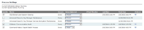
Figure 3 - 6. Process Settings Window
The column headings include the following functions:
•Enable. Select the check box for the appropriate process to enable that function. Clear the check box to disable the function.
•Name. This column displays each function.
•Occurs. This column displays the interval at which each function runs.
•Time/Interval. This column allows the user to select a time for the appropriate function from the corresponding drop-down list.
•Offset Minutes. Offset Minutes. Minutes after the clock-aligned interval, used to set the exact time for the Incremental Daily Reads Extract to run. If this setting is not 0, the extract will run at exactly this number of minutes after the top of the hour, and every interval thereafter.
•Last Run. This column displays the last date and time that each process was run.
•Next Run. This column displays the date and time of the next scheduled process.
•Actions. This column displays a Run Now icon. Click the icon to immediately run the desired process.
•History icon in the Warehouse Update Process row. Click the History icon to view the Process History (Last 30 Days) window. If there are any failed links in the Status column, click the link to view the reason why the task did not run.
The Actions column also displays a Run now icon in most rows. Click the icon to immediately run the desired process.
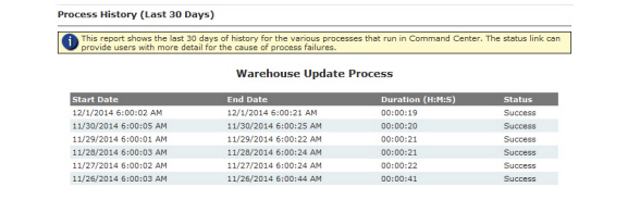
Figure 3 - 7. Process Settings Window
2.The following processes are displayed for editing. Settings displayed will vary based on license activation.
|
Process Name |
Description |
|---|---|
|
Abandoned User Session Cleanup |
Clean-up abandoned user sessions. |
|
Advanced Security Key Manager Maintenance |
This scheduled task manages the process of destroying old keys from the Data Protection Manager (DPM) and deleting it from the Key Manager database. As keys expire, or devices are forced to roll keys or devices migrate to an encryption mode where their individual keys are no longer needed (Open/AES CTR with system key), Command Center flags the devices as candidate for this maintenance task.
|
|
Advanced Security Key Manager Service Encryption Maintenance |
This scheduled task manages the encryption of the keys stored in the Key Manager database. The process first has to decrypt the key with the KEK that was used to encrypt it, then re-encrypt with the new active KEK and lastly update the Key Manager database with the new results. It is throttled by a System Setting Maximum Key Manager Maintenance Process Batch Size which establishes how many keys to process each time the task runs. |
|
Assign IP Address |
Assigns IP Addresses to a collector. |
|
CIM 2nd Edition Event Incremental Extract |
|
|
Collector Communication Audit |
This process monitors for disconnected Collectors which drives the Collector Communication Delay alert. |
|
Command History Report Batch Process |
Default value is enabled and will default to run every 4 hours. |
|
Command Timeout Monitoring Service |
Identifies commands that have not responded invoking business logic appropriate to the command. |
|
Commands Workflow |
Several Commands require that command center receive a confirmation that they were received. This task's responsibility is to retry those commands or move the endpoint to failed if the max retries is reached. The commands this task will retry: Send Meter Program, Time Zone Settings (SET UTC (GMT) offset, Set DST enabled), and Send Temporary Schedules (for demand reset). |
|
Confirm RF Demand Reset |
This process runs to check if there are any pending demand resets for the current day for which Command Center has not yet received the demand reset data. |
|
Daily Maintenance |
Performs system maintenance tasks that are required to be run once a day. Select a time for the daily maintenance process. The times are available in 15 minutes intervals. The default selection is 6 P.M. |
|
Daily RF Reads Status Process |
Updates the information being displayed on the RF Daily Reads Status report. The default selection is 1 hour. |
|
Dashboard Data Aggregation |
Provides switch command counts. Excludes data older than 7 days. The default 7 days can be changed by Landis+Gyr Technical Support. |
|
Dashboard Data Synchronization |
Synchronization. Re-aggregates dashboard data in case it is out of sync with daily activities. |
|
Deployment Status |
Defines how frequently the RF Deployment Status Report is updated. Select the desired interval to run the deployment status process. The choices range anywhere from every minute to every 24 hours. The default selection is every two hours. |
|
Event Gap Reconciliation |
Perform event gap reconciliations. |
|
Event Gap Reconciliation Retry |
Retries event gap reconciliation requests, where no response has been received. |
|
Gap Reconciliation |
Performs Gap Reconciliation for self read and interval data. |
|
Gap Reconciliation Retry |
This process setting allows the user to establish whether gaps retrieval will be re-attempted, and if so, how frequently the process will run. |
|
Get Daily Weather Related Data |
Used to gather the last seven days of weather data from the NOAA (National Oceanic and Atmospheric Administration) weather service for the zip code entered on the Organization Information window. |
|
Incremental Daily Reads Extract |
Select the frequency at which the Incremental Daily Read Extract will be processed. The default schedule is every hour. Offset can be a user define time period. For example, if the frequency is set to one hour and the offset is ten minutes, the extract will run ten minutes past the top of the hour. And this will occur consistently even if an extract has been run manually. |
|
Incremental Interval Extract |
Select the frequency at which the Incremental Interval Extract will be processed and the associated offset. The default schedule is every 2 hours. |
|
Message Communication Report Batch Process |
Process daily message communication report batch process. |
|
Meter Configuration Extract |
This process generates data for Meter Configuration Extract. All the devices which have changes to their configuration since the last process run are included. |
|
Meter Exception Batch Process (Oracle only) |
Select the frequency and time to run the Meter Exception Batch Process. |
|
Network Device Configuration Extract |
This process generates data for Network Device Configuration Extract. All the devices which have changes to their configuration since the last process run are included. |
|
Network Endpoint Communication Audit |
The audit process runs after every configurable period and if the communication is delayed or restored, it will generate the Network Communication Delay or Network Communication Restore events for Repeaters. |
|
Not Logging Devices Extract |
This process generates the data for Not Logging Devices Extract. All the devices which are not sending reads since last x days are included. |
|
Offline Database Service Daily Processing |
Process daily offline database Service. |
|
Publish Site Statistics |
Publish Site Statistics allows Command Center to gather statistics at a certain time each day. The times are available in 15 minutes intervals. The default selection is 5:00 A.M. |
|
Readings Consolidation |
Consolidate Readings |
|
Reconfigure RF Endpoints |
Select the desired time from the drop down list box. The Reconfigure Endpoint process is the process in which Command Center communicates with the collectors as to which endpoints need to be re-configured. The reconfigure endpoints settings determines how frequently the system will send commands directing reconfiguration to the endpoints. |
|
RF Collectors Set Time |
N/A. Should not be enabled. |
|
RF Gas/Water Reconfiguration Process |
Will be displayed if the Gas and/or Water endpoint license is active. When a gas or water module registers or the configuration group is changed, the RF Gas/Water Reconfiguration Process will send configuration changes to the module. |
|
RF Network Low Energy Endpoint Communication Check |
This process periodically checks all gas modules in Normal and SecConfig status. If a module’s Last Good Packet time stamp is older than current time minus the Gas Lost Communication Threshold setting, the process moves the module to Lost Communication status. |
|
RF Network Layer Calculation |
Select the frequency at which network layer information will be updated. |
|
RF Network Security Reconfiguration |
This process checks for endpoints that require security configuration updates. |
|
RF Registration Verification |
The RF Registration Verification looks for endpoints that have been sent the SetWAN command, but have not yet delivered confirmation. Endpoints meeting this criteria shall be sent a new SetWAN command. |
|
RF Scheduled Demand Reset Workflow |
Select the interval to run the RF Scheduled Demand Reset Workflow. |
|
Scheduled Data Collection |
|
|
Scheduled Reading Gap Detection |
When enabled, the Scheduled Reading Gap Detection reading process will ignore the gap between start date and end date determined in the Organization Settings. |
|
Set RF Gas GMT offset |
Will be displayed if an RF Gas endpoints license is active. |
|
Set RF Water GMT offset |
Will be displayed if an RF Water endpoints license is active. |
|
Update Endpoint Ranges |
This task runs once a week if enabled (default) and downloads the endpoint ranges from Landis+Gyr. If there has been new endpoint ranges allocated the system will be updated. Select the day of the week and the start time from their respective drop-down lists. The default selections are Saturday at 9:00 A.M |
|
Update Groups after Module Change Out |
Perform assignment of groups for endpoints whose module changeout is done. |
|
Warehouse Update Process |
Select how often to run the warehouse update process. The times are available in 15 minutes intervals. The default selection is 3:00 A.M. |
|
Weekly Maintenance |
Weekly maintenance helps clear out old database logs. Select how often to run the weekly maintenance process. The times are available by a selected day in 15 minutes intervals. The default selections are Sunday at 9:00 A.M. |
3.Click the Save button to save any changes.
CAUTION: System Settings should not be modified without assistance by Landis+Gyr.
This window is used to adjust system functionality settings.
1.Click Setup > System Settings.
The System Settings window will be displayed.
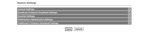
Enter the following settings:
|
Name |
Description |
|---|---|
|
Alert Processor Timer Interval |
The number of milliseconds between consecutive executions of the alert processor timer. The default is set to 600000 or 10 minutes. |
|
Archive Timeout |
Establishes the MS SQL Timeout setting in seconds to be followed for the Command Center archive process. The default setting is 0, indicating no timeout. The Minimum setting is 1. The Maximum setting is 32767. After the MS SQL timeout is reached, the archive process will abort. |
|
Base Queue File Path |
Indicated the base path of the queue. |
|
Billing Extract Timeout |
Establishes the MS SQL timeout in seconds to be followed for the billing extract process. The default setting is 180 seconds. The minimum setting is 1. The maximum setting is 32767. A value of 0 indicates no timeout. After the MS SQL timeout is reached, the billing extract process will abort. |
|
Cache Enabled |
Enables caching on the dashboard. |
|
Capture Alert Statistics |
This setting is used to track statistics for the alerts processor. It captures the number of times a category of alert was issued on the day. Enabling this setting could have a performance impact. |
|
Check OA Predicted Outages |
Enables Command Center to check outages predicted by the Outage Analysis. |
|
Concurrent GE Processes |
Determines the number of simultaneous Collectors that will be downloaded at any given time. This does not affect processing only collecting the raw data. This number should be less than or equal to the number of Collector Queue Threads. |
|
Concurrent Process GE Processes |
Determines the number of Collector readings that will be processed at one time. The default is one and should not be changed. |
|
Confidence Percent Change |
Determines in the percent confidence algorithm. Increasing this value causes confidence to increase given the same signal value. The default value is set to 20. |
|
Confidence Percent Default |
Determines the most confident percentage supported (given no calculation is available) and also functions as a maximum value returned from the web service. |
|
Confidence Percent Trip |
Determines the percent of the 3 day average a current signal must decay to in order to switch from Restoration to Outage status. Likewise this value is used to determine the point where a device’s current signal value must increase to in order to be reported as a Restoration. The default value is 70. |
|
Deadlock Retry Attempts |
Establishes the number of times a SQL batch will be retried if there is a deadlock error. |
|
Deadlock Retry Wait |
Establishes the number of seconds between SQL deadlock retries. |
|
Update Endpoint Voltage Type |
When enabled (selecting the check box), this turns on/off the automated update of existing endpoints to set voltage type during the Update Endpoint Ranges process. |
|
Event Driven Cache Expiration |
Check box to enable Event Driven Cache Expiration. |
|
Event Processor Threads |
Sets the number of Event Processor Threads. The minimum setting is 0. The maximum setting is 50. A value of 0 indicates that the Event Processor will start up running the non multi-threaded code. |
|
Exclude Usage Monitored From No kWh |
When enabled excludes meters that are a member of a usage monitoring group from being displayed on the Suspect Meter, “that have reported No kWh Usage for at least” report. |
|
Expiration Check Interval |
The time interval in minutes after which the dashboard window gets the updates from the server. The default is set at 1 minute. |
|
Force Cache Refresh |
Check box to enable Foce Cache Refresh. |
|
Group Address Modify Group Threshold |
Determines the threshold number of endpoint addressed group reconfigurations beyond which a Group addressed command would be issued. This applies only to group modifications like change in packet sequence or a TOU rate schedule. |
|
HTTP Version |
Determines the HTTP header used when communicating with Collector. |
|
License URL |
Allows the utility to provide a custom URL that will override where Command Center goes to update the license. |
|
Log Enabled |
Determines whether web service communication is logged to file. |
|
Log File Purge Interval |
Determines how long Command Center will keep log files before deleting them. |
|
Log HTTP Headers |
Determines whether HTTP headers will be logged in web service communication. |
|
Log Collector Communications |
Determines whether Collector communication will be logged. |
|
MSWS Get Service Location Update Enable |
If enabled, and if CIS integration is enable, and if the CIS has implemented the GetServiceLocationByServLoc web method, a web method call is made and the service location data is updated in CC for the meter being added to service. |
|
MSWS Meter Add Notification Disable |
Acts as a override switch to disable the auto deployment feature used in the MultiSpeak interface with the customer information system (CIS). The endpoint will stay in Inventory. |
|
MVRS Organization |
Determines which organization the MVRS process will use. |
|
Organization Info Expiration |
Establishes the length of time the Organizational Settings will be cached in memory before getting them from the database again. |
|
Process Readings Queue |
Establishes the message queue where readings will be processed. |
|
Process Readings Queue File Path |
Establishes the partial path where readings queue messages are stored. |
|
Queue Wait Length |
Establishes the initial number of seconds for the wait period between attempts to communicate with a Collector. |
|
Queue Wait Length Multiplier |
Establishes the multiplier applied to the prior total wait time between attempts to communicate to the Collector to determine the next wait time. |
|
Queue Wait Steps |
Determines the number of times a wait state will occur before giving up on the message. |
|
Queue Wait Timeout |
Determines the number of seconds to wait before timing out while listening for messages in command queue (will sleep then try again). |
|
Retry TS1 Legacy Commands |
Check box to enable Retry TS1 Legacy Commands. |
|
RF Broadcast Command (Excluding Firmware Downloads) Send Count |
The number of times Command Center will repeat the command when sending a broadcast command (excluding endpoint firmware download, meter firmware download and HAN firmware download) to the collector. |
|
RF Max Reconfigure Endpoints Per Collector |
The maximum number of endpoint addressed set configuration group commands that Command Center will send to one collector at a time. |
|
RSS Command Expiration |
Enter RSS Command Expiration time in minutes. |
|
Scheduler Remoting Port |
Default setting is 30 minutes. |
|
Sender Address |
Establishes the sender address to be used by the SMTP server when sending e-mails generated from Command Center The sender address is used for both e-mail alerts and when the e-mail function is used to send a Service History Report. |
|
Service User |
Determines the Command Center user that the service will use when sending commands. |
|
Site Statistics URL |
Allows the user to provide a custom URL that will override where site stats will be published. |
|
Collector Change Lookback |
Determines the number of days to look back to process a Collector change. |
|
Collector Command Queue |
Determines the message queue for commands sent to the Collector. |
|
Collector Command Queue File Path |
Determines the partial path for where the command queue messages are stored. |
|
Collector Event Queue |
Determines the message queue for events sent to the Collector. |
|
Collector Event Queue File Path |
Determines the partial path for where the event queue messages are stored. |
|
Failed Event File Storage |
Enable to store packets that fail processing. These packets can be resubmitted to be attempted to be processed again. |
|
Failed Event Storage File Path |
Displays the file path to the storage file. |
|
General Response Event Queue |
Queue used to isolate general response messages from other events |
|
General Response Event Queue |
|
|
General Response Queue File Path |
|
|
Collector Info Expiration |
Establishes the length of time the Collector settings will be cached in memory before retrieving them from the database again. |
|
Collector Message Header |
|
|
Collector Queue Flag |
|
|
Collector Queue Threads |
|
|
SQL Command Timeout |
Length of time Command Center will wait before allowing a SQL batch timeout. This setting is not used for every SQL batch. |
|
Asynchronous Processing Endpoint Threshold |
The maximum number of endpoint addressed asynchronous commands that Command Center will send before sending group addressed for the scheduled command Asynchronous Processing. |
|
Endpoint ID Ranges URL |
Allows the utility to provide a custom URL that will override where Command Center looks for updated serial number ranges. |
|
Use BCP |
This option will allow the data warehouse to use the bcp.exe instead of the bulk copy SQL command during the update process. |
|
Rollover based on number of dials on meter |
Used during readings processing for RF meters |
|
Endpoint Statistics Collection |
When enabled turns on the data collection of device radio statistics. |
|
NMM Health Status - Number of Neighbours |
Minimum number of neighbors required for the endpoint for calculating the health status. |
|
NMM Health Status - SNR |
Minimum Signal to noise value required for the endpoint for calculating the health status. |
|
Message Communication Statistics |
When enabled turns on the data collection of network latency. |
|
SQL Command Timeout |
Length of time Command Center will wait before allowing a SQL batch timeout. This setting is not used for every SQL batch. |
|
Asynchronous Processing Endpoint Threshold |
The maximum number of endpoint addressed asynchronous commands that Command Center will send before sending group addressed for the scheduled command Asynchronous Processing. |
|
Endpoint ID Ranges URL |
Allows the utility to provide a custom URL that will override where Command Center looks for updated serial number ranges. |
|
Use BCP |
This option will allow the data warehouse to use the bcp.exe instead of the bulk copy SQL command during the update process. |
|
Rollover based on number of dials on meter |
Used during readings processing for RF meters |
|
Readings Performance Monitors |
|
|
IP Capability |
Enables/Disables the IP Capacity |
|
IP Version |
IP Version allows user to choose either IPv4 or IPv6. By IP-enabling, the Gridstream system will provide an IP interface to the external systems through the Command Center system to allow the use of regular IP-based network tools in order to access the devices in the Gridstream network. |
|
Network Class |
This field facilitates a user to choose what network class he/she wants for his/her network based on the size of their network. |
|
Base IP Address |
This is a “read only” field which is auto populated on selecting the network class and is used to calculate the IP address range. |
|
Subnet Mask |
Subnet Mask determines the number of hosts for a network. This field is a dropdown from where user can select the desired subnetmask. |
|
IP Address Range |
This field is a “read only” field and calculated based on the Base IP Address and the selected subnet mask. |
|
IP Assignment Batch Size |
There is a scheduled task for IP Assignment process, this field determines how many endpoints will be picked by this process for IP Address assignment in one task execution. The value of this field ranges from 100 to 500,000, its default it value 500,000. |
|
Traditional Encryption |
Enables traditional encryption. |
|
Auto Generate Meter Configuration Groups |
Enable or disable auto configuration group feature. |
|
Endpoint Auditing |
Enable to audit user actions done on endpoints e.g. Adding new endpoints to system changing existing endpoints. |
|
Auto Generate Meter Configuration Groups |
Enable or disable auto configuration group feature. |
|
Endpoint Auditing |
Enable to audit user actions done on endpoints e.g. Adding new endpoints to system changing existing endpoints. |
|
Scheduled Demand Reset Window to send Commands |
The number of days prior to a scheduled demand reset date to send commands to the meters. |
|
Scheduled Demand Reset Window to send Commands |
The number of days prior to a scheduled demand reset date to send commands to the meters. |
|
Confirm RF Demand Reset Max Retry Days |
|
|
MultiSpeak Batch Size |
Maximum Number of Devices returnable through MultiSpeak webservices |
|
Incremental Daily Reads Extract Lookback |
When the Incremental Daily Reads Extract is enabled, the default look-back period of ‘0’ includes rows for today, starting at midnight. Set this to ‘1’ to include rows for today plus yesterday. Set this to ‘2’ to include rows for today plus yesterday plus the day before yesterday. Maximum look-back period is ‘2’. |
|
RF Scheduled Demand Reset Midnight Offset Logic |
Enable application of offset to the RF meters scheduled demand reset midnight time |
|
RF Scheduled demand reset midnight offset to add to minimum time sync value |
The offset to add to the meter's time sync X value to determine the midnight offset for scheduled demand reset. The maximum value of time sync X plus the offset will be enforced at 59 seconds. |
|
On-Demand Readings and On-Demand Reset Data in Data Extract/Data Streaming - Electric |
When checked, conventional Data Extract (register reads) will include off-cycle demand reset, manual demand reset data, and on-demand readings for both incremental and standard (non-incremental) extracts and Data Streaming subscriptions for Electric Meters. |
|
On-Demand Readings Data Extract/Data Streaming - Gas |
When checked, conventional Data Extract (register reads) will include on-demand readings for both incremental and standard (non-incremental) Gas Meter extracts and Data Streaming subscriptions. |
|
On-Demand Readings Data Extract/Data Streaming - Water |
When checked, conventional Data Extract (register reads) will include on-demand readings for both incremental and standard (non-incremental) Water Meter extracts and Data Streaming subscriptions. |
|
Configuration Group Assignment |
Enable the setting to assign meter configuration group based on manually imported program mapping. The setting will override the group assignment procedure during INIT Push. |
|
Support for Comm Module Change Out |
Enable to perform module change out. This setting shall allow user to perform the communication module change out for an existing service. |
|
Support for Meter Only Import Files |
This setting allows users to import AMI ready meters in the database and identify the association with the module during the registration process. |
|
Daily Reads Report Aggregation Lookback Days |
The number of days back the daily reads report data will be aggregated. |
|
Daily Reads Report Blackout Begin Time |
Start time during which the RF daily reads process will not aggregate the data for the report. |
|
Daily Reads Report Blackout End Time |
End time after which the RF daily reads process will aggregate the data for the report. |
|
Automatically Retrieve Manual Demand Reset Data |
Enable to automatically retrieve demand reset data when a manual demand reset occurred. The default setting is enabled. |
|
Show Enhanced Event View on Advance Search Page |
|
|
Sync Demand Reset Schedule when Billing Cycle Changes |
Enable this to Synchronize Demand Reset Schedule when Billing Cycle changes. The default setting is Disabled. Changes to this setting will be recorded in the Daily Activity report and the System Settings audit report. |
|
Allow DA Traffic in Lost |
|
|
Incremental Billing Extract Lookback |
When the Incremental Billing Extract is enabled, the default lookback period of 0 includes rows for today, starting at midnight. Set this to 1 to include rows for today and yesterday. Set this to 2 to include rows for today, yesterday, and the day before yesterday. The maximum lookback period is 2. |
|
Dashboard Endpoint Alerts Lookback Days |
The number of days Endpoint Alerts will be displayed on the AMI Dashboard. The minimum setting is 3. The maximum setting is 365. |
|
Incremental Interval Extract Lookback Days |
|
|
Name |
Description |
|---|---|
|
Processing attempts |
The number of times to repeat the processing of each step of the firmware download. |
|
Max Request Lookback Interval |
Maximum number of days the service looks back for any pending broadcast firmware downloads that are created or stopped for any reason. |
|
Blackout start time |
Begin time to stop the broadcast firmware download process from issuing commands. |
|
Blackout end time |
End time to stop the process from issuing commands. |
|
Time Out Threshold Duration |
The period of time to look back for active requests for a collector. NOTE: Only for users with a LGSupport role. |
|
Download retry count |
It is the maximum number of re-processing attempts allowed for a broadcast firmware download request after a processing failure. |
|
Broadcast Collectors Filter Paging Size |
The maximum number of collectors that will be displayed in the Broadcast Collectors filter, per page, between 1 and 10000. |
|
Time Out Threshold Duration |
The period of time to look back for active requests for a collector. |
|
Broadcast Collectors Filter Paging Size |
The maximum number of collectors that will be displayed in the Broadcast Collectors filter, per page, between 1 and 10000. |
|
Name |
Description |
|---|---|
|
Devices to Configure during Security Configuration |
This setting is used to configure endpoints during security configuration process based on security configuration state. |
|
Key Generation File Path |
Specifies the directory on the Primary Application Server where Key Generation Files are placed. |
|
Local Download Threshold |
Number of hours that shall be used to determine whether a download command was issued by the host or via a local download. |
|
Maximum User Authentication Attempts |
Defaulted to 5. Will lock the user out of their account if the exceed that number of authentication attempts entered here. |
|
Security Configuration Batch Size |
The max number of endpoints that Command Center should send the update security status command. The default setting is 200. |
|
Security Configuration Retry Count |
The number of times Command Center will attempt to configure the endpoint's security before moving it to Failed. The default setting is 3. |
|
Security Configuration Collector Threads |
The maximum number of security configuration collector threads to utilize. |
|
Security Configuration Blackout Start Time |
This is the begin time to stop the security configuration process from running during the defined period of time. |
|
Security Configuration Blackout End Time |
This is the end time to stop the security configuration process from running during the defined period of time. |
|
Maximum Key Maintenance Process Batch Size |
The maximum number of devices per collector to perform key maintenance on each time the key maintenance scheduled task runs. |
|
Maximum Key Maintenance Process Threads |
The maximum number of threads to perform key maintenance tasks which involves destroying keys in key manager and deleting keys from cache database. |
|
Maximum Cache Maintenance Process Batch Size |
The maximum number of keys in the cache database to encrypt with the active key encryption key each time the cache maintenance scheduled task runs when a new key encryption key is generated. |
|
Maximum Key Manager Maintenance Process Batch Size |
The maximum number of keys in the key manager database to encrypt with the active key encryption key each time the key manager maintenance scheduled task runs when a new key encryption key is generated. |
|
Maximum Crypto Operation Threads |
The maximum number of threads that will process a batch of concurrent crypto operations such as encryptions or decryptions. |
|
Maximum Concurrent Key Manager Sessions |
The maximum number of concurrent key manager sessions per process involving key storage and retrieval. |
|
Maximum Concurrent HSM Sessions |
The maximum number of concurrent HSM sessions per process involving message signing and ECIES decryptions. |
|
Enable Key Manager Service |
Enable this setting to use the Key Manager Service. Requires Key Manager Service database and components to be installed prior to enabling. |
|
Reuse Signatures |
Enables reuse of signatures when the payload of downstream packets for multiple endpoints is the same. |
|
Low Energy Endpoint Settings |
|
|
Maximum Security Configuration Commands per Batch per Run |
This is the maximum number of security reconfiguration commands processed for each batch per run by the Low Energy Endpoint Security Reconfiguration process. The default value is 20. |
|
Maximum Security Configuration Commands per Parent per Run |
The maximum number of security reconfiguration commands sent to the parent devices of Low Energy Endpoints by the Security Reconfiguration process per run. The default value is 2. |
|
Maximum Security Configuration Retries |
The maximum number of times a failed security reconfiguration command is resent to a Low Energy Endpoint before moving the endpoint to failed security status. The default value is 3. |
|
Maximum Security Configuration Parallel Threads |
The maximum number of parallel threads for the Low Energy Endpoint Security Reconfiguration process. The default value is 5. |
|
Name |
Description |
|---|---|
|
Update last packet received on command response |
Update last packet received on command response |
|
Outage/Restore alert processor is immediate |
Outage/Restore alert processor is immediate |
|
Insert INTGMSG record for async response/event |
Insert INTGMSG record for async response/event |
|
Create Command Response Record for integration messages |
Create Command Response Record for integration messages. |
|
Validate Issuer Event ID for HAN Commands |
Validate Issuer Event ID for HAN Commands. |
|
Schedule Distribution |
Select this setting to enable remote distribution of scheduled tasks that support being executed across remote application servers. |
|
Name |
Description |
|---|---|
|
Block Size (RF) |
This is the size of each block in the firmware image that will be sent to the endpoint in the RF network. |
|
Block Transmit Interval Unicast (RF) |
This is the time interval in seconds between consecutive steps in a unicast download in the RF network. |
|
Block Transmit Interval Multicast (RF) |
This is the time interval in seconds between consecutive steps in a multicast download in the RF network. |
2.Click the Save button.
Data Streaming allows near real time readings data transfer from Command Center readings processes to third-party applications utilizing the CIM 2nd Edition standard interface. These readings can be streamed to several external systems. Reading types available for streaming include:
• Register reads
•Interval Load Profile reads
•On Demand reads (Optional)
The Data Streaming component must be installed using the Centralized Installer. Please see ICMS Installation Add-On: Data Streaming Package Specifics, publication number 98-2622 Rev AA, for installation instructions.
Command Center requires a license for Data Streaming.
1.Enable Data Streaming by selecting Setup > External Integration and then expanding the Integration Suite - Web Based Services accordion.Check the box for Data Streaming Service.

Figure 3 - 9. Enable Data Streaming Service
2.Select Setup > Data Streaming. The Data Streaming Summary page will open.
From this page, Data Streams can be added, edited or deleted.
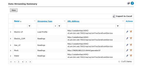
Figure 3 - 10. Data Streaming Summary
To create a new Data Stream, do the following:
1.From the Data Streaming Summary page, click New.
2.Enter a Name for the new data stream.
3.Select a Streaming Type from the drop-down list:
•Readings
•Load Profile
4.Enter the Publish URL path.
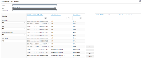
Figure 3 - 11. Create New Data Stream
5.Select the Data Definitions to stream. Use the > or < symbols to add or remove data definitions. Filter the data definitions options by using the following filters:
•Commodity
•All
•Electric
•Water
•Gas
•Type
•All
•Interval
•Register
•Unit of Measurement
•All
•Amps
•Amp-Hours
•CCF
•CF
•W
•Wh
•VAr
•VArh
•vA
•VAh
•W/VA (Power Factor)
•Volts
•Volts-Hours
•CM
•US GAL
•Time of Use
•All
•Non-TOU
•TOU
6.Click Save or Cancel.
To edit an existing Data Stream, do the following:
1.From the Data Streaming Summary page, click the Edit (pencil icon) for a data stream. the Create New Data Stream page will open.
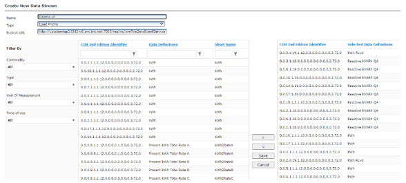
Figure 3 - 12. Edit Data Stream
2.Add or remove data definitions as described in “Create a New Data Stream” on page 53.
3.Click Save. A confirmation message will be displayed stating that the Data Stream Saved Successfully.
To delete an existing Data Stream, do the following:
1.From the Data Streaming Summary page, click the Delete (X icon) for a data stream.
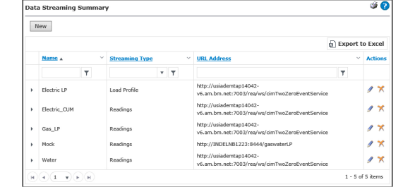
Figure 3 - 13. Delete Data Stream
2.A pop up message will ask Are you sure you would like to delete the data streaming entry.
3.Click OK.
IP Address Support for Endpoints
Command Center supports IP addressability for endpoints. IP has been identified as one of the key protocols that will serve as the foundation to build interoperability within the smart grid.
In reflection of this, the RF Mesh solution has the ability to assign IP addresses to each node in the network (endpoints, Routers, Collectors) as well as supporting IP commands.
Command Center acts as an IP-operations center by managing all IP exchange between external applications (i.e. HP Open View, Advent Net, etc.) and the endpoints. For this purpose, Command Center manages the IP address assignment for each RF node, process all IP requests, and respond to these requests in IP packet structure.
The commands supported by this function are:
•Ping
•SNMP – Get Endpoint Configuration
•SNMP – Get Endpoint Info
NOTE: To take advantage of this feature, access is managed through the Gridstream Integration Suite.
NOTE: To enable this feature go to Setup > System Settings page - enable IP Capability.
NOTE: The IP address assigned to each endpoint will appear on the Endpoint Information Window.
The ANSI C.12.22 standard is supported in Command Center by using Command Center as an ANSI C.12.22 Master Relay and Gateway.
Command Center will assign an ANSI C.12.22 ID (called App Title in the standard language) to each endpoint and will create ANSI C.12.22 extended tables (decades 12 and 13) for each endpoint within the Command Center Database.
This will allow Command Center to process ANSI C.12.22 requests and provide responses using the standard packet format.
The following are the C.12.22 services supported:
•Identification
•Registration
•De-registration
•Read
•Write
•Trace
•Resolve
NOTE: To take advantage of this feature access is managed through the Gridstream Integration Suite.
1.Click Setup > C12.22 Operation > C12.22 Settings to display the C12.22 Settings window.
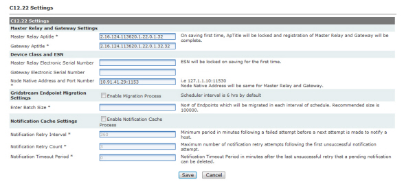
Figure 3 - 14. C12.22 Settings
a.Master Relay and Gateway Settings.
•Master Relay Aptitle. On first save this field will be locked.
•Gateway Aptitle. On first save this field will be locked.
b.Device Class and ESN.
•Master Relay Electronic Serial Number. On first save this field will be locked.
•Gateway Electronic Serial Number. On first save this field will be locked.
•Node Native Address and Port Number. Node Native Address will be same for Master Relay and Gateway.
c.Gridstream Endpoint Migration Settings.
•Enter Batch Size. This is the number of Endpoints which will be migrated in each interval of schedule. Recommended size is 100000.
d.Notification Cache Settings.
•Notification Retry Interval. Minimum period in minutes following a failed attempt before a next attempt is made to notify a host.
•Notification Retry Count. Maximum number of notification retry attempts following the first unsuccessful notification attempt.
•Notification Timeout Period. Notification Timeout Period in minutes after the last unsuccessful retry that a pending notification can be deleted.
NOTE: Migration process will begin only when an Authentication Host or Notification host is made available to the System.
A user with Security Administrator permissions is created during the Command Center software installation, and, initially, only this user will have access to Command Center.
NOTE: Landis+Gyr recommends that the utility immediately elect an additional individual with rights to user management.
The User Access function allows the Security Administrator to add or edit customized access roles as well as create users and administer user functions.
User Roles define the functionality that groups of individuals at the utility will be provided in the Command Center. As a part of the AMI deployment, the utility should determine which individuals will have access to Command Center, and which functions they will need to perform their duties.
NOTE: To view all default user roles, please see the current Landis+Gyr Command Center User Roles and Permissions spreadsheet. Some roles and permissions listed on the spreadsheet and in this document are license specific and may not be available in your version of Command Center.
Following is the procedure to view the existing Roles:
1.Select Setup > User Access > Roles.
2.The Roles window will open displaying all existing user roles, shown in Figure 3 - 15.
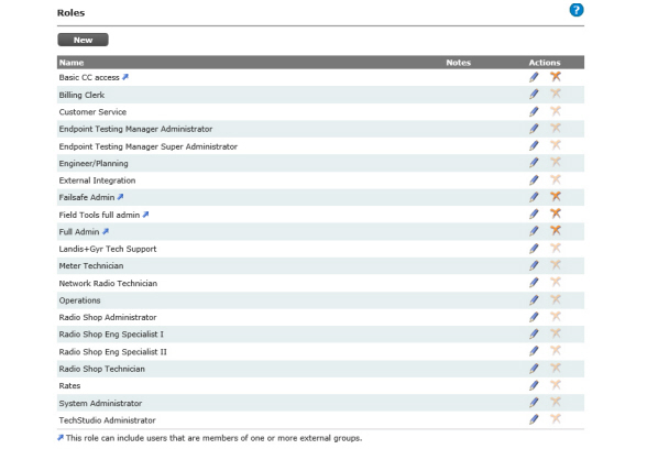
CAUTION: To ensure optimal support from Landis+Gyr, the database is populated with a user role - Landis+Gyr Tech Support - for use by the Landis+Gyr Technical Support team. This role should not be edited or deleted.
The following actions may be performed
•Edit. This function allows for editing an existing role.
•Delete. This function allows for deleting an existing role. If users have been assigned to the role, this option will be unavailable.
NOTE: When a new role is created, or an existing role is modified and the permission is changed, an entry will be made in the User Roles Management Audit Report.
Seeded roles may be used by the utility, or the utility may choose to define custom roles for its users.
Following is the procedure to create a new Role:
1.Click New. The Role Management window will open, shown in Figure 3 - 16.
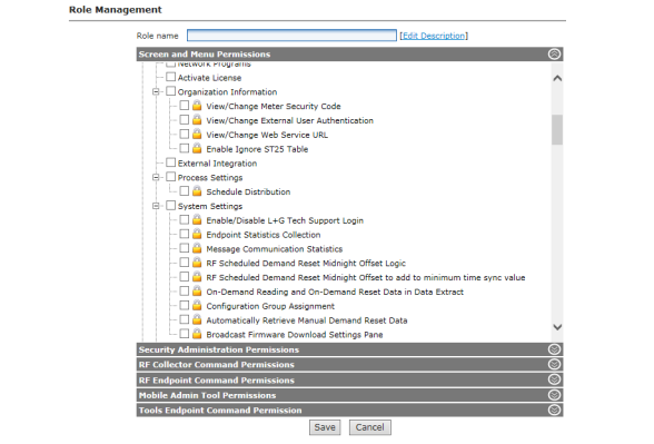
Figure 3 - 16. Role Management
2.Enter a Role name. The role name must be unique to the organization.
3.Click the Edit Description link to add notes to describe the role (optional).
4.Select individual permissions from each of the following:
a.Screen and Menu Permissions
The Screen and Menu Permissions section lists all of the menu options available in Command Center. Select the check-box next to the menu option to allow access for the user role. The top-level can be checked to select all sub-entries. Menu options denoted by a lock, indicate that the user may be provided read only access.
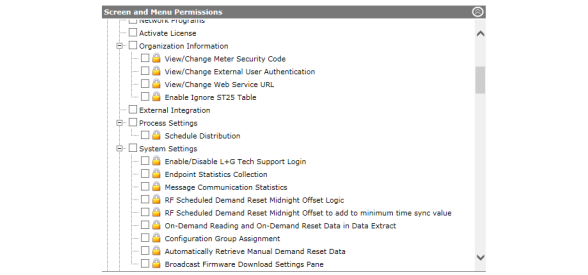
Figure 3 - 17. Screen and Menu Permissions
b.Security Administration Permissions
The Security Administration Permissions section lists all of the menu options available in Command Center. Select the check-box next to the menu options to allow access for the user role.
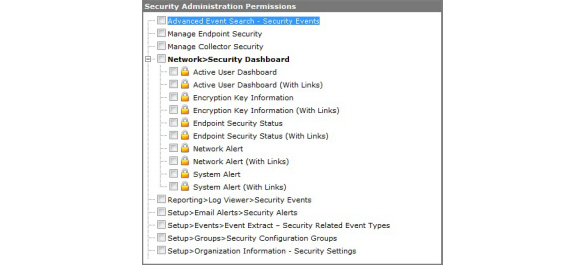
Figure 3 - 18. Security Administration Permissions
c.RF Collector Command Permissions
All of the available collector commands will be listed in the RF Collector Command Permissions section. Select the check-box next to the collector command to allow access for the user role to execute the command.
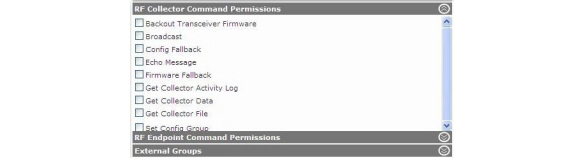
Figure 3 - 19. RF Collector Command Permissions
d.RF Endpoint Command Permissions
All of the available Endpoint commands will be listed in the RF Endpoint Command Permissions section. Select the check-box next to the Endpoint command to allow access for the user role to execute the command.
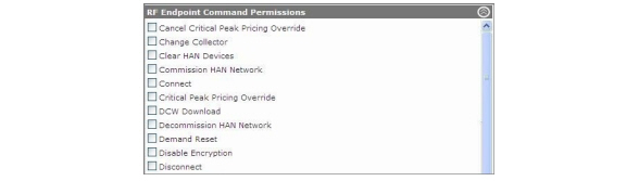
Figure 3 - 20. RF Endpoint Commands Permissions
e.Click External Groups to associate external groups with this role.
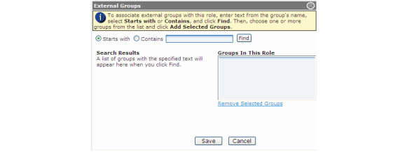
Figure 3 - 21. External Groups
NOTE: The Organization Information setting External User Authentication must be enabled to activate this functionality.
To associate external groups with this role:
i.Enter text from the Group name as it is identified in Active Directory.
ii.Select Starts with or Contains.
iii.Click Find.
iv.Choose one or more groups from the list.
v.Click Add Selected Groups.
f.Mobile Admin Tool Permissions
Click Mobile Admin Tool Permissions, shown in Figure 3 - 22, to select the privileges to be granted to users of RadioShop, Endpoint Testing Manager and TechStudio.
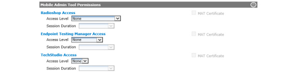
Figure 3 - 22. Mobile Admin Tool Permissions
i.RadioShop Access.
•Access Level. Select the level of permission to be granted to users assigned to this role.
•Session Duration. The session duration controls the amount of time a user’s credentials are cached on the local machine. During the session duration the RadioShop user may log into RadioShop without authenticating with Command Center.
•Temporary. 8 hours
•Strict Control. 24 hours
•Tight Control. 10 days
•Normal. 32 days
•Relaxed. 187 days
•No Expiration. Does not require user to periodically login it authenticate.
•MAT Certificate. Select this check-box to grant a MAT certificate for use in communication with devices using Advanced Security configuration. This option will only be displayed if the utility is licensed for Advanced Security.
ii.Endpoint Testing Manager Access.
•Access Level. Select the level of permission to be granted to users assigned to this role. Refer to “Mobile Admin Roles and Permissions” on page 64 for further details.
•Session Duration. The session duration controls the amount of time a user’s credentials are cached on the local machine. During the “session duration” the Endpoint Testing manager user may log into ETM without authenticating with Command Center.
•Temporary. 8 hours
•Strict Control. 24 hours
•Tight Control. 10 days
•Normal. 32 days
•Relaxed. 187 days
•No Expiration. Does not require user to periodically login it authenticate.
•MAT Certificate. Select this check-box to grant a MAT certificate for communication with devices using Advanced Security configuration. This option will only be displayed if the utility is licensed for Advanced Security.
iii.TechStudio Access.
•Access Level. Select Yes to grant login privileges.
•Session Duration. The session duration controls the amount of time a user’s credentials are cached on the local machine.
•Temporary. 8 hours
•Strict Control. 24 hours
•Tight Control. 10 days
•Normal. 32 days
•Relaxed. 187 days
•No Expiration. Does not require user to periodically login it authenticate.
•MAT Certificate. Select this check-box to grant a MAT certificate for communication with devices using Advanced Security configuration. This option will only be displayed if the utility is licensed for Advanced Security.
|
Mobile Admin Tool |
User Role |
Permissions |
|---|---|---|
|
RadioShop |
Administrator |
Gives the user the highest level of access to RadioShop. The administrator is typically the manager. |
|
RadioShop |
Engineering Specialist 2 |
Gives the user same privileges as Administrator without the security rights. |
|
RadioShop |
Engineering Specialist 1 |
Gives the user full software rights, excluding password administrator and sending AES key to 5.X endpoints. This privilege can run any canned report/function and can make changes to reports/ functions via the GUI. |
|
RadioShop |
Technician |
User will not be allowed to send DCWs to any radio. This privilege can run any canned report/function, but cannot write anything to the radio. |
|
ETM |
Administrator |
Gives the user the highest level of access to ETM |
|
ETM |
Super Admin |
Gives the user the same rights as Administrator, and can zero out pulse counts on both residential and commercial gas meters. |
|
TechStudio |
Yes |
Grants login privileges. |
|
TechStudio |
No |
Denies login privileges. |
g.Tools Endpoint Command Permission
Select from available options to control user access to the menus, pages and commands for TechStudio. These options are not enabled by default.
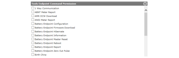
Figure 3 - 23. Tools Endpoint Command Permission
5.Click the Save button to save the role.
The Security Administrator must create a user profile for each individual requiring access to Command Center.
Following is the procedure for viewing existing users in the system:
1.Select Setup > User Access > Users.
2.The Users window will open.
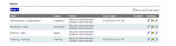
The Users window displays all active user accounts, and provides the ability to edit a user profile, reset passwords, archive users, and configure new user profiles.
Following is the procedure for creating a new user profile:
1.Select Setup > User Access > Users. The Users window will appear, shown previously in Figure 3 - 24.
2.Click New. The User Management window will open, shown in Figure 3 - 25.
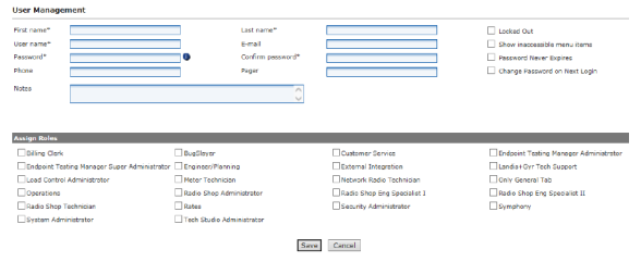
Figure 3 - 25. User Management
Enter all required fields (indicated by an asterisk).
•First Name. Must be one or more alpha characters.
•Last Name. Must be one or more alpha characters.
NOTE: The first name/last name combination must be unique to the organization.
•User Name. The user name is not case sensitive and must not exceed 20 characters.
•E-mail. This field is not required, however, an e-mail address is necessary for users wishing to setup e-mail alerts.
•Password. Enter the user’s password. The minimum number of character allowed is configured in the Organization Information settings. The user’s password must contain one upper case, one lower case, one alphanumeric, as well as one digit.
•Confirm Password. Retype the password.
•Phone. Enter the user’s telephone number (optional)
•Pager. Enter the user’s pager number (optional)
•Notes (optional). Enter any notes associated with the user
•Role Assignments. Select one or more roles to assign to this user.
•Locked Out. By default, when a user attempts to login to Command Center five times with an unrecognized user name or password, the user will be locked out of the system. This setting is applicable to Command Center credentials only.
uSystemSetting: The default number of log-in attempts may be configured in the System Settings “Maximum User Authentication Attempts”
•Show inaccessible menu options. Select this check box to allow users to see menu items that are not part of their role. If selected, when the user logs into Command Center, all menu options will be displayed, but those menu options to which the user has not been granted permissions will be grayed out and unavailable.
•Password Never Expires. Selecting this option allows for over-riding the global Organization Information setting Maximum Password Age. If selected, the user will never be required to change his/her password. This is especially useful for users created for integration to other software, for example GSIS.
•Change Password on Next Login. Selecting this option will cause the user to be required to change their password the next time they login to Command Center. Best practice when first setting up users, would be to force them to change their password on next log-in so that they may select a password only known to them.
•System Owner. When the System Owner check-box is selected all existing tenant groups are automatically assigned.
3.Click the Save button to save the new user.
For auditing purposes, inactive users may not be deleted from the system, they must be archived.
Following is the procedure to archive a user:
1.Click the Archive icon for the selected user in the Users window. A windows dialog box will open, asking for confirmation of the archive action.
2.Click OK. The user has now been archived.
Show Archived Users
1.Click the Show Archived Users check box on the User window.
2.The User window will refresh and archived users will appear with a red check mark in the corresponding row under the Archived heading.
NOTE: To un-archive a user, clear the Archived check box within the user’s profile, clear the locked out check box, reassign a role and reset the user’s password.
Reset User Password
When necessary, the Security Administrator (or a user assigned user management privileges) may reset a user’s password:
1.Click the Reset password icon for the selected user in the Users window.
2.Enter the New Password.
3.Re-enter the new password to confirm.
4.Click the Save button to save the changes.
Audit Reports provide a method to track changes made to Organization Settings, Collector Settings, System Settings, as well as logs of daily activity, user log ins, and when collectors have been archived. Audit Reports will only be displayed for those individuals who have been granted Security Administrator rights.
1.Click Setup > User Access > Audit Reports to display the Audit Reports window.
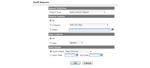
2.Select one of the following reports from the Report Type drop-down list, reports will vary depending on licenses:
a.Daily Activity Report. Displays a description of the activity, the date of the activity, the login user and details of the activity.
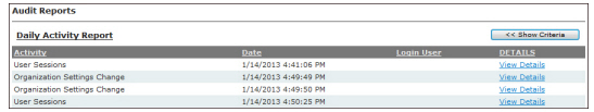
Figure 3 - 27. Daily Activity Report
b.Collector Archived Report. The Collector Archived report shows all Collectors that have been archived. Collectors can be archived on the Setup > Collectors page. Collectors can only be archived if there are no associated endpoints.
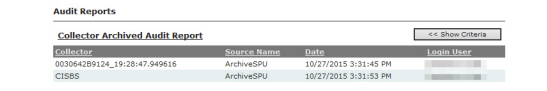
Figure 3 - 28. Collector Archived Audit Report
c.Collector Settings Change. Displays collector name, setting name, new value, old value, date of change and the login of the user who made the change.
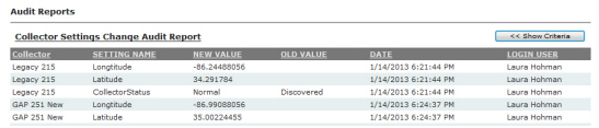
Figure 3 - 29. Collector Settings Change Audit Report
d.Critical Commands. Displays login of user who issued the command, date it was issued, the command that was issued, meter number, endpoint serial number and the collector name.
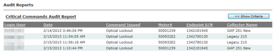
Figure 3 - 30. Critical Commands Audit Report
e.Data Extract Change > SubReport Type.
•Incr Daily Reads Extract
f.Endpoint Configuration > SubReport Type. Displays the SubReport activity, meter number, endpoint serial number, date the command was issued, the login of the user who issued the command the a detail view of the activity.
•All
•Billing Cycle Added
•Billing Cycle Changed
•Billing Cycle Deleted
•Endpoint Added
•Endpoint Added to Billing Cycle
•Endpoint Archived
•Endpoint Billing Cycle Changed
•Endpoint Changed
•Endpoint Deleted
•Endpoint Removed
•Endpoint Removed from Archive
•Endpoint Removed from Billing Cycle
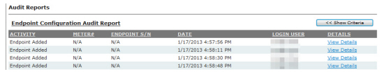
Figure 3 - 31. Endpoint Configuration Audit Report
g.File Transfer Management Audit Report. This report displays file transfer import operations of DA devices, such as streetlight controllers, by sub report type. The report displays the activity, login user, date, file name and firmware type. Sub Report filters include:
•All
•Transfer File Deleted
•Transfer File Imported

Figure 3 - 32. File Transfer Management Audit Report
h.Group Management > SubReport Type.
The Group Management Audit Report records when devices are moved from one tenant group to another. This report is designed to be used for auditing the following groups in Command Center:
•All
•Collector Groups
•Load Control Groups
•Status Groups
•Endpoint Group Type: Disconnected Groups, Low Signal Quality Groups, Maintenance Groups, Multi Utility Monitoring Groups, Outage Disabled Groups, Permanent Switch Groups, Planned Outage Groups, Quarantine Groups, SIM Management Platform Outage Reporting Groups, Temp Switched Groups, User Defined Groups, Validation Groups, Zero Usage Groups
•Tenant Groups
•User Defined Addressing Groups
•Virtual Addressing Groups
i.Import Operations > SubReport Type. Displays the login of the user who issued the command, date the command was issued, the SubReport activity type and the name of the .csv file.
•All
•Collector Installation File Imported
•Collector Manufacturer File Imported
•Customer Information File Imported
•Endpoint ID Ranges Updated
•Mass Archive Endpoints File Imported
•Mass Inventory Endpoints File Imported
•Meter Installation File Imported
•Meter Manufacturing File Imported
•Meter Program Mapping File Imported
•Tool Data Imported
•Update Performance from Tool
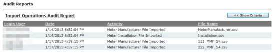
Figure 3 - 33. Import Operations Audit Report
j.Login Failures: Invalid Password > SubReport Type. Displays the SubReport Type activity selection, the name of the user who attempted to login with an invalid password.
•All
•CC Invalid Password
•ETM Invalid Password
•GUTS Invalid Password
•RadioShop Invalid Password
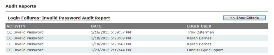
Figure 3 - 34. Login Failures: Invalid Password Audit Report
k.Login Failures: Invalid Username > SubReport Type. Displays the SubReport Type activity selection, the name of the user who attempted to login with an invalid username.
•All
•CC Invalid Username
•ETM Invalid Password
•RadioShop Invalid Username
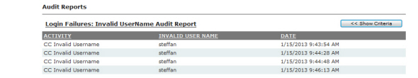
Figure 3 - 35. Login Failures: Invalid Username Audit Report
l.Meter Program Management
The Meter Program Management option allows the user to select to view meter programs that were imported, archived or re-instated.
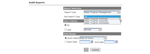
Figure 3 - 36. Meter Program Management Sub-Reports
•Meter Program Imported Sub-Report
The Meter Program Imported Audit Report, shown below, provides the user a log of Meter Programs that have been imported.
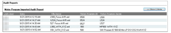
Figure 3 - 37. Meter Program Imported Audit Report
•Meter Program Archived Sub-Report
The Meter Program Archived Audit Report, shown below, provides the user a log of Meter Programs that have been archived.
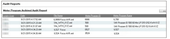
Figure 3 - 38. Meter Program Archived Audit Report
•Meter Program Reinstated Sub-Report
The Meter Program Reinstated Audit Report, shown below, provides the user a log of Meter Programs that have been reinstated.
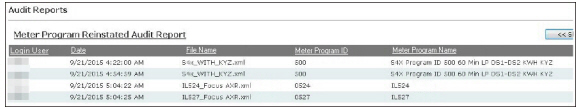
Figure 3 - 39. Meter Program Reinstated Audit Report
m.Meter Readings Quality Changed > Sub-Report Type.
The Meter Readings Quality Changed report. Sub-menu reports include Reading Quality Changed to Billable and Reading Quality Changed to Non-Billable.
•All
•Reading Quality Changed to Billable
•Reading Quality Changed to Non-Billable
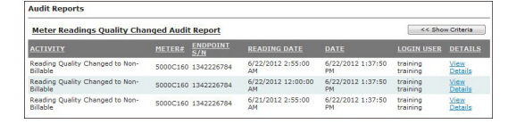
Figure 3 - 40. Meter Readings Quality Changed Audit Report
n.Organization Settings Change. Displays the name of the activity, the setting name, the date the change was made, the login of the user who changed the setting and a detailed view of the report.
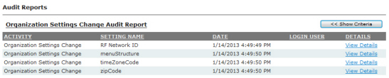
Figure 3 - 41. Organization Settings Change Audit Report
o.Process Settings Change. Displays the name of the activity, the process name, the date the change was made, the login of the user who changed the setting and a detailed view of the report. Sub-reports include:
•All
•Process Settings Disabled
•Process Settings Enabled
•Process Setting Interval Changed
•Process Setting Manually Run
•Remote Connect Halted Process Restarted
•Remote Disconnect Halted Process Restarted
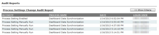
Figure 3 - 42. Process Settings Change Audit Report
p.Security. Displays details for a user action, the date that the action took place, the login information of the person who performed the action and the user ID.
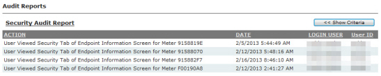
Figure 3 - 43. Security Audit Report
q.System Settings Change. Displays the setting name, the new value of the setting, the old value of the setting, the date the setting was changed and the login of the user who changed the setting.
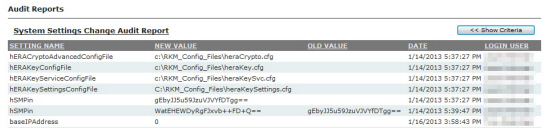
Figure 3 - 44. System Settings Change Audit Report
r.Tool User Logins. Displays details of when a tool user logged in, the user name and the date the login occurred. Sub-reports include:
•All
•ETM Successful Login
•Maintenance Terminal, (a.k.a. GUTS) Successful Login
•RadioShop Successful Login
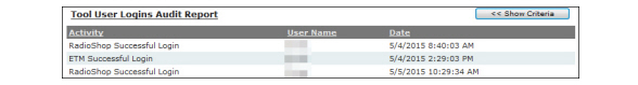
Figure 3 - 45. Tool User Logins Audit Report
s.User Account Management. Displays the Sub-Report Type activity selected, user name of the user, the date of the activity, the login of the user who made the change, and details of the action.
•All
•Tenant Group Assigned to User
•Tenant Group Removed From User
•User Archived
•User Changed
•User Created
•User Locked Out
•User Password Reset
•User Reinstated
•User Unlocked
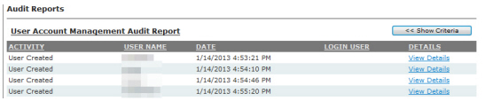
Figure 3 - 46. User Account Management Audit Report
t.User Roles Management. Displays the SubReport Type activity selected, the role name of the user, the date of the activity, the login of the user who made the change and the details of the action.
•All
•User Role Changed
•User Role Created
•User Role Deleted
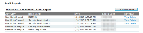
Figure 3 - 47. User Roles Management Audit Report
u.User Sessions. Displays the user ID, the session action, the name of the user, the session start time, the session end time, the number of days of the session, the session length, terminated by and logtime.
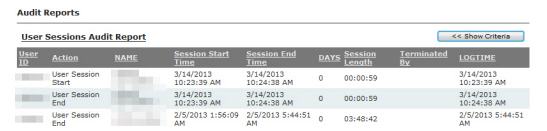
Figure 3 - 48. User Sessions Audit Report
3.Select from the following Device Criteria on which to base the report, if applicable:
•All. Select the All radio button to include all collectors in the report.
...or...
Collector. Select the Collector radio button and then choose a Collector from the drop-down list to include only the selected Collector in the report.
...or...
Meter. Enter the meter number in the Meter field or click the Find a Meter icon and browse to a meter location. This will include only the selected meter in the report.
4.Select from the following User Criteria on which to base the report:
•All. Select the All radio button to include all users in the report.
...or...
User. Select the User radio button and then choose a user from the drop-down list to include only the selected user in the report.
5.Select a Date Range from the following:
•Quick Select. Choose a time frame from the drop-down list
...or...
Start Date. Select a start date by clicking on the Start Date calendar icon, then select an end date by clicking on the End Date calendar.
6.Click OK to display the report.
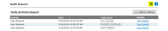
Figure 3 - 49. Sample Audit Report
7.Click ![]() (Figure 3 - 49) to save the report as a.csv file.
(Figure 3 - 49) to save the report as a.csv file.
Command Center users can be authenticated by three different authentication providers:
1.Command Center (Internal) Authentication. This is the current means of authenticating users and relies on credentials stored in the Command Center Central Services database. For system security, the administrator should be the only person that has access to administer roles and their associated permissions. See “Command Center Authentication” on page 76.
2.SAML (Security Assertion Markup Language) Authentication. See “SAML Authentication” on page 78.
3.External User Authentication. Users can log in via their domain user name, also used to log in to Windows, either by entering it directly to Command Center or implicitly by using Internet Explorer while logged on to their Windows desktop. See “External User Authentication” on page 82.
NOTE: When a user logs in to the Command Center, only the menus that the user has access to will be displayed.
NOTE: The administrator should define the various roles and those roles should be assigned immediately after installing Command Center. The system will be seeded with basic roles that may be edited by the administrator if desired.
The administrator will need to establish a user profile for each employee that has access to Command Center. This is also where the roles are assigned for access to the Command Center.
1.Click Setup > User Access > Users to display the Users window.
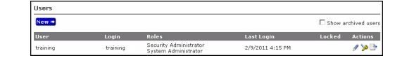
Figure 3 - 50. Users Window
2.Click the New button to display the User Management window.
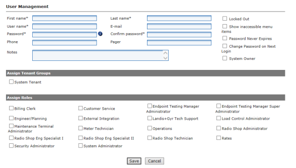
Figure 3 - 51. User Management Window
3.At a minimum, the required fields must be filled in.
•First Name. Must be one or more alpha characters.
•Last Name. Must be one or more alpha characters.
NOTE: The first name and last name combination must be unique to the organization.
•User Name. Must be unique to the organization. The user name is not case sensitive. The user name must not exceed 20 characters.
•E-mail. Enter the contact’s e-mail address. This e-mail address is used for sending alerts via the Alert Manager.
•Password. Passwords are case sensitive and must contain a minimum of six characters that consist of at least 1 upper case, 1 lower case and 1 non-alphanumeric character, as well as 1 digit.
•Confirm Password. Retype the entered password.
•Phone. Enter the user’s telephone number. This can be a mobile or land-line telephone number. This field is optional and for informational purposes only.
•Pager. Enter the user’s pager number. This field is optional and for informational purposes only.
•External user name. This is the user name on the Active Directory server.
•Notes. Enter any notes associated with the user.
•Role Assignments. Allows the administrator to assign available role(s) that were created earlier in this chapter to this user.
•Locked Out. This box will be checked when a user has unsuccessfully attempted to log in to the system five times with an unrecognized password. The Locked Out status will be indicated by a red check mark on the Users window.
Only users assigned the “Roles” permission will be able to view and modify the Locked Out check box.
The administrator can re-enable the login by clearing the check box.
•Show inaccessible menu options. Select this check box to allow users to see menu items that aren’t a normal part of their role. The inaccessible menu items are displayed, but grayed-out.
•System Owner. When the System Owner check-box is selected all existing tenant groups are automatically assigned.
4.Click the Save button to save the user.
Before SAML Authentication can be enabled, the Security Administrator role will need to be edited.
1.Click Setup > User Access > Roles to display the Roles window.
2.Click the Edit icon for the Security Administrator role.
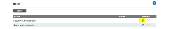
Figure 3 - 52. Roles
3.On the Role Management page, expand the Security Administration Permissions section.
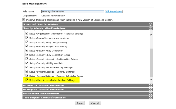
Figure 3 - 53. Role Management Window
4.Click the Setup>User Access>Authentication Settings box to enable the Authentication Settings function for the Security Administrator role.
5.Click Save.
Enable SAML Authentication Settings
1.Select Setup > User Settings > Authentication Settings to display the Authentication Settings page.
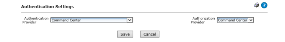
Figure 3 - 54. Authentication Settings
2.Select SAML (Security Assertion Markup Language) from the Authentication Provider drop-down list. Additional fields will be displayed.
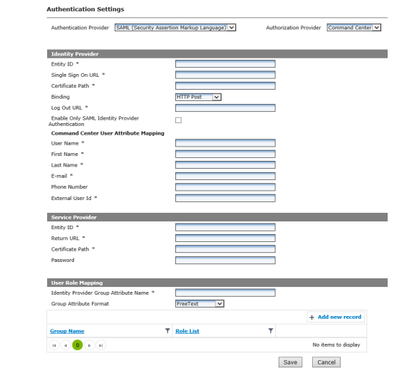
Figure 3 - 55. Authentication Settings - Identity Provider
3.Select the Authorization Provider from the drop-down list. Command Center is the default value.
4.Enter the following Identity Provider information:
•Entity ID
•Single Sign On URL
•Certificate Path
•Select the Binding type from the drop-down list.
•HTTP Post (default setting)
•HTTP Redirect
•Log Out URL
•Enable Only SAML Identity Provider check-box. Unchecked by default, check to enable.
NOTE: Once checked and saved, the box cannot be unchecked.
Enter the Command Center User Attribute Mapping information.
•User Name
•First Name
•Last Name
•Phone Number
•External User ID
5.Enter the Service Provider information.

Figure 3 - 56. Service Provider
•Entity ID
•Return URL
•Certificate Path
•Password
6.Enter User Role Mapping information:
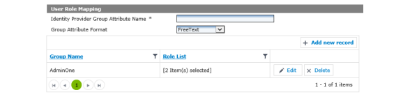
Figure 3 - 57. User Role Mapping
a.Enter the Identity Provider Group Attribute Name.
b.Select the Group Attribute Format from the drop-down list.
•FreeText
•ActiveDirectory
7.Click Add new record.
a.Enter a Group Name and select associated Roles from the Role List, click Update.
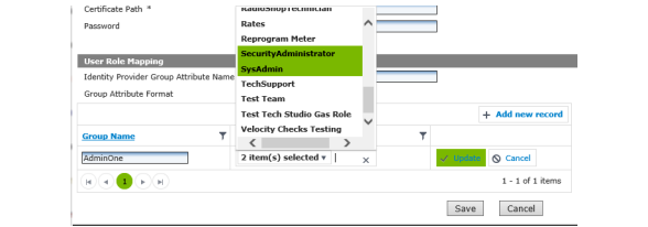
Figure 3 - 58. Role Mapping
The Group Name will be added to the table of available groups. Multiple groups may be created.
b.Click Edit to make changes to the group.
c.Click Add new record to make an additional group.
8.Click Save.
Since Active Directory supports user groups, a user's membership in an external group can indicate membership in a Command Center role.
New Installation
When an external user is authenticated for the first time, a new Command Center user can be created automatically if the user has membership in an external Command Center group, i.e., one that belongs to one or more Command Center roles.
Prior Installation
A new Command Center user should not be created when the individual already has a Command Center login. Instead, the individual's external credentials should be linked to their existing login. This resolution of external and Command Center identities can be performed in two ways:
1.Manual Resolution. For each user account that will be externally authenticated, an administrator adds the external identity (e.g., AD domain and user name) to the Command Center user profile. The same external identity may not be added to more than one user account.
2.User-Assisted Resolution. When a user logs in with external credentials that Command Center does not recognize, the user will be offered a list of user names that are not already linked. The user can then:
•Choose one to associate with their external identity. In this case, they must enter the correct password for the selected user.
WARNING: The Command Center web server (where the UI portion is installed) must be a registered server on the active directory domain.
External User Authentication Setup
1.Click Setup > Organization Information to display the Organization Information window.

Figure 3 - 59. Organization Information
2.Enable External User Authentication by selecting the Enabled check-box.
3.Click the Save button.
Add External Integration to Command Center Roles
1.Click Setup > User Access > Roles to display the Roles window.
2.Click the Edit icon for the selected Role to display the Role Management window.

Figure 3 - 60. Role Management Window
3.Check the External Integration check-box to enable.
4.Click the Save button.
Add External Integration to Command Center Roles
1.Click Setup > User Access > Roles to display the Roles window.
2.Click the Edit icon for the selected Role to display the Role Management window.
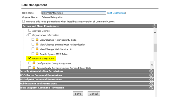
Figure 3 - 61. Role Management Window
3.Check the External Integration check-box to enable.
4.Click the External Groups bar to display the External Groups search.
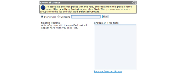
Figure 3 - 62. Role Management Window - External Groups
5.Select either the Starts with or Contains radio button, enter a search term, and click the Find button.
6.From the Search Results box (shown below) click to select a group (Control-click to select multiple groups).
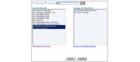
Figure 3 - 63. Add Selected Groups
7.Click the Add Selected Groups link to add the selected groups to the Groups In This Role box.
8.Click the Save button.
All users are granted the right to change their password. Changing the password is not required, nor forced after a number of days.
NOTE: Command Center will only allow password changes to the Command Center identity, not an external authentication identity. The Change Password window will not be available to users if External Authentication is enabled.
Following is the procedure for changing a user password:
1.Select Setup > Change Password. The Change Password window will open.
2.Enter the Current Password.
3.Enter the New Password.
4.Re-enter the new password to Confirm New Password.
Multiple Security Settings establish how passwords are managed in Command Center. Organization Information settings may be viewed and changed by selecting Setup > Organization Information > Security Settings.
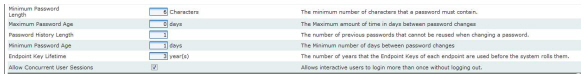
Figure 3 - 64. Security Settings
•Minimum Password Length. This setting allows the Security Administrator to specify the minimum number of characters a password may contain. The default value is 6, and may be a value from 6 - 19.
•Maximum Password Age. This setting allows the Security Administrator to establish the frequency at which users must change their password. When a user's password expires the user will be required to change the password, and will not be able to access Command Center until they do so. It is best practice to expire passwords every 30 to 90 days.
NOTE: An over-ride, specifying that a user's password never expires, can be configured for individual users.
•Password History Length. This option allows the Security Administrator to specify mechanism to specify how many unique new passwords must be associated with a user before an old password can be reused. The value must be between 0 and 30 passwords. A value of 0 results in no password check. If the user attempts to reuse a password, the error message You are trying to reuse a password you have used previously. Please select a password that you have not used previously. will be displayed.
•Minimum Password Age. This setting allows the Security Administrator to specify the minimum amount of time, in days, that a user must use a password before they are allowed to change it. If the user attempts to change their password before the Minimum Password Age is reached the error message The minimum time between password changes has not been met. You cannot change your password at this time will be displayed. The default value is 1. The Minimum Password Age must be less than the Maximum Password Age, unless the Maximum Password Age is set to 0, indicating that passwords will never expire. If the Maximum Password Age is set to 0, the Minimum Password Age can be set to any value between 0 and 1000.
•Allow Concurrent Users Sessions. This setting allows the Security Administrator to select whether or not all Command Center users may have either a single or multiple sessions open at one time. By default, this setting is enabled.
The following two functions allow the individual user to change their own passwords and set up E-mail alerts.
Change Passwords
The Change Password window allows the individual user to change passwords.
NOTE: Changing passwords is not required and is not forced after a certain number of days.
NOTE: This menu option will not be available if using External Authentication.
1.Click Setup > Change Password.
The Change Password window will be displayed.

Figure 3 - 65. Change Password Window
NOTE: Passwords are case sensitive and must contain a minimum of six characters that consist of at least 1 upper case, 1 lower case and 1 non-alphanumeric character, as well as 1 digit.
2.Type the user’s Current Password.
3.Type the user’s New Password.
4.Retype the user’s new password to Confirm New Password.
5.Click the Save button to save the changes.
The E-mail Alert Manager will allow the Command Center user the ability to select the method and thresholds they wish to utilize for notifications of user definable events.
The E-mail Alert Manager notifies the users of the following category of events:
•Endpoint Status Alerts
•Collector Alerts
•Endpoint Validation Alerts
•Endpoint Alerts
•General Endpoint Alerts
•RF Security Alerts
•System Error Alerts
•Velocity Threshold Alerts
The present method for delivery of alerts include individual e-mail notification.
The system administrator can view and modify user subscriptions but is not able to subscribe other users.
NOTE: Microsoft Internet Information Services (IIS) must be installed on the computer before using the E-mail Alerts module.
WARNING: Once a threshold has been crossed, the user won’t be notified each time the system checks for crossed thresholds. When a count falls beneath a threshold and then crosses it again, a new alert will be triggered.
1.Click Setup > E-mail Alerts.
The E-mail Alerts window will be displayed.
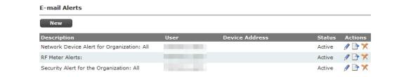
NOTE: All users that want to set up alerts must first have an e-mail account created.
2.In the E-mail Alerts window, click the New button.
The Select an Alert window will open.
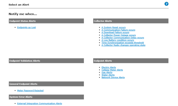
Figure 3 - 67. Select an Alert Page
The Select an Alert window contains the following categories to choose from:
a.Endpoint Status Alerts. Endpoint Status Alerts are issued when the endpoint status changes or if the threshold number of endpoints in a specific status is exceeded. An organization user or a group can subscribe for alerts at an endpoint level, organization level, collector level or by location. Specify the endpoint alert threshold when making a selection other than by meter.
NOTE: When defining thresholds for email alerts for when Endpoints go Lost, meters that are assigned to a Status Group (Planned Outage or Disconnected) will be included in the threshold count, even though the event is suppressed within the user interface.
b.Collector Alerts. Collector Alerts emails are issued when specific events or errors occur for a Collector. Select a Collector, a location, or an organization.
c.Endpoint Validation Alerts. Endpoint Validation email alerts notify when the exceptions specified in the Validation Groups setup by the utility are triggered.
d.Endpoint Alerts. Endpoint Alerts are issued when meter alarm or advisory conditions (events) occur or if the threshold number of alarm or advisory conditions is exceeded.
e.General Endpoint Alerts. General Endpoint email alerts are issued when specific events or errors occur for routers or meters.
f.RF Security Alerts. RF Security Alerts emails will be sent when specific security related events are logged by the system.
g.System Error Alerts. Sends an email when an External Integration Command Error is logged.
h.Velocity Threshold Alerts. The generation of email alerts is used to notify the users when the command velocity threshold is exceeded.
3.Select any alert to open the Alert Filter window to sign up for an email alert.
a.Select the Alert Filter option.
NOTE: Some alerts will have additional filter choices.
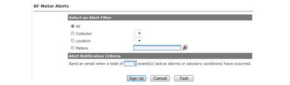
Figure 3 - 68. RF Network Device Alerts
•All. To filter the alert by all endpoints.
•Collector. To filter the alert by a Collector.
•Location. To filter the alert by location.
•Meters. To filter the alert by an individual meter. Enter a meter number or click the Find a Meter icon to browse to a meter location.
b.Alert Notification Criteria. Enter an alert threshold. When this threshold is exceeded, an e-mail alert will be sent to the users that signed up for this alert notification. The default threshold is one.
c.Click the Sign Up button to subscribe to this alert. The new alert window will open displaying the newly created alert subscription.
Test E-mail Alerts
To send a test message to the subscribed user’s e-mail address, use the following procedure:
1.Click Setup > E-mail Alerts.
The E-mail Alerts window will be displayed.
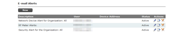
Figure 3 - 69. E-mail Alerts Window
2.Click the Edit icon of the desired alert.
3.In the selected Endpoint Status Alert window, click the Test button.
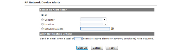
Figure 3 - 70. E-mail Alerts Test
4.Clicking the Test button sends a test message to the user’s e-mail address.
A test message should arrive shortly in the user’s e-mail.
NOTE: The alert will remain in the Alerts window in the Active or Inactive state until the alert is activated or deactivated again or until the user deletes the alert.
Organization Locations allows the utility to establish the hierarchical organization structure it will need to allow for multiple geographic regions, districts, and offices to be managed by one or more system administrators. Establishing multiple regions will allow the user logged into the system to choose to filter data in order to view only substations, groups, endpoints, etc. that are specific to the user’s own region, district, or office.
The geographic locations can then be chosen by clicking on the Filter icon on most Command Center screens.
NOTE: All Organization Locations are optional. To specify Organization Location Level Names see Organization Information.
If the optional data filtering is desired, follow these instructions to establish the data filtering hierarchy.
1.Click Setup > Organization Locations.
The Organization Locations window will be displayed.

Figure 3 - 71. Organization Locations Window
NOTE: Under the following headings Location Level Names will be referred to by their default settings of Region, District, and Office.
Each region name must be unique to this organization. You can add as many regions to the organization as desired.
1.To add a region, click the Add Region link to display the Region window.

2.Enter a region name in the Name field.
3.Enter an optional region description in the Description field.
4.Click the Save button.
Each District name must be unique to this organization. You can add as many districts to the organization as desired.
1.Click the Add District link to display the District window.

Figure 3 - 73. District Window
2.Select a region from the drop down box.
3.Enter a district name in the Name field.
4.Enter an optional district description in the Description field.
5.Click the Save button.
Each Office name must be unique to this organization. You can add as many offices to the organization as desired.
1.Click the Add Office link to display the Office window.

2.Select a district from the drop-down box.
3.Enter an office name in the Name field.
4.Enter an optional office description in the Description field.
5.Click the Save button.
Archiving data will enhance the performance of Command Center. This is accomplished by specifying that data older than a user-specified date be archived as a scheduled task.
Data older than the specified date will be archived from the following Command Center functions:
•Interval Data History
•User Session History
Landis+Gyr recommends scheduling Archive Settings as a weekly task. It is best run during a period of inactivity (such as a weekend morning).
1.Click Setup > Archive Settings.
The Archive Settings window will be displayed.
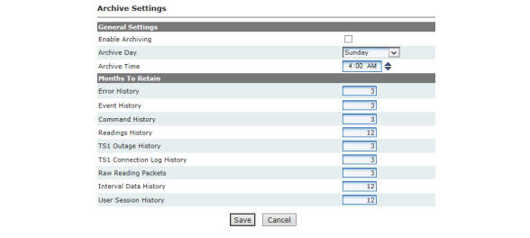
Figure 3 - 75. Archive Settings
2.General Settings.
All regions are displayed by default. If you would like to filter the archive by selected regions, click the Filter icon in the upper-right corner of the window.
•Enable Archiving. Select the Enable Archiving check box to enable the archiving function. (Default is off).
•Archive Day. Select any desired day of the week to schedule the archive from the Archive Day drop-down list.
•Archive Time. Select the Archive Time.
•Click to highlight the hour. Click the up or down arrows to change the hour.
•Click to highlight the minutes. Click the up or down arrows to change the minutes.
•Double-click AM or PM, or highlight AM or PM and click the up or down arrows, to toggle between the two selections.
3.Months to Retain.
Select the number of months of data to retain for the listed categories. This means that if you select 12 (the default choice), the last 12 months of data will be retained and the remainder will be archived. The valid choices are any number of months greater than zero.
4.Click the Save button to save your selections and enable archiving.
NOTE: The archived data is saved to the Archive database that was set up during the Command Center installation.
Events Integration provides an interface to communicate alerts, flags and events logged by Command Center to an external software (MDMS, ODS, etc).
The Event Extract allows Alerts, Flags and Events from Command Center to be exported for use in other software programs.
1.Click Setup > Events > Event Extract to display the Scheduled Event Extract window.
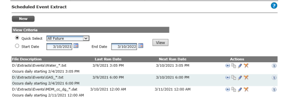
Figure 3 - 76. Scheduled Event Extract Window
2.Click the New button to display the new Scheduled Event Extract window.
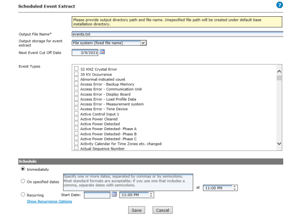
Figure 3 - 77. New Scheduled Event Extract Window
uOrganization Information Setting: A general setting for the Base Installation Directory is captured during Command Center installation or upgrade.The data extracts in Command Center will use the Base Installation Directory for data extracts in the absence of a directory being specified.
3.Enter an Output File Name.
4.Choose the Output storage for event extract from the drop down
5.Enter or select the Next Event Cut Off Date.
6.Select the Event Types to include in the extract file.
7.Under Schedule select one of the following:
•The Immediately radio button.
...or...
•On specified dates radio button and then specify one or more dates separated by commas or semicolons in the text box. Most standard date formats are acceptable. If you use a date format that includes a comma, separate the dates with a semicolon.
...or...
•To Auto Schedule the Scheduled Read:
i.Select the Recurring radio button and click the calendar icon to select a start date. If you want to change the specified start time, highlight the hour and type a different hour or use the up and down arrows to change the hour. Highlight the minutes and type different minutes or use the up and down arrows to change the minutes. To select AM or PM, click the AM icon to toggle between AM and PM.
ii.Click the Show Recurrence Options link to expand the window to display the recurrence options.
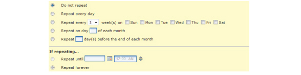
Figure 3 - 78. Recurrence Options
The Recurrence Options window expansion displays the following Scheduled Read options. Click the corresponding radio button to make your selection.
•Do not repeat. The Scheduled Read will occur once.
•Repeat every day. The Scheduled Read will occur daily.
•Repeat every [1-2-3-4] week(s) on Sunday through Saturday. The Scheduled Read can be set to repeat every 1, 2, 3, or 4 weeks on any, or all, of the days of the week.
•Repeat on day [ ] of each month. The Scheduled Read can be set to repeat on the same date of each month. Enter a number from 1 to 31.
•Repeat [ ] day(s) before the end of each month. The Scheduled Read can be set to repeat every month on a specified number of days before the last day of the month.
If you elect to repeat the Scheduled Read, the following two options are also available.
•Repeat until [ ]. The Scheduled Read can be set to repeat until the user specified date by clicking the calendar icon and selecting the end date for the Scheduled Read. To change the end time, highlight the hour and type a different hour. Highlight the minutes and type different minutes. To select AM or PM, click the AM icon to toggle between AM and PM.
•Repeat forever. The Scheduled Read can be set to repeat forever unless or until you change the end date.
8.Click the Save button.
The Event Groups window displays the event groupings seeded in Command Center.
Following is the procedure for viewing the Event Groups:
1.Select Setup > Events > Event Groups to display the Event Groups window shown.
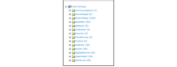
2.Click the Plus sign adjacent to a folder to view the associated events.
The event priority function allows the utility to create a priority that defines the frequency at which events will be extracted to the external software, for use in configuring event subscriptions.
Following is the procedure for defining event priorities:
1.Click Setup > Events > Event Priority to display the Event Priority Window.
Click the New button to display the Event Priority window.
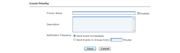
2.Enter a Priority Name. This name must be unique to the organization.
3.Select the Enabled check box to immediately enable this event priority.
4.Enter a Description for this priority (optional).
5.Select the desired Notification Frequency from the choices below. This is the frequency at which events assigned to this priority will be written to the extract file.
•Send Event Immediately. Select this option to write the event to the extract file immediately
•Send Events in Groups Every _ Minutes. Select this option to and enter the number of minutes to write events to the extract file at the specified frequency.
6.Click the Save button.
The Events Subscriptions window allows the user to assign events to specific event priorities, created previously, and provide the URL, user name, and password to the subscribing external system.
Following is the procedure for creating a new Event Subscription:
1.Click Setup > Events > Event Subscription to display the Event Subscription window.
Click the New button to display the Event Subscriptions Details window.
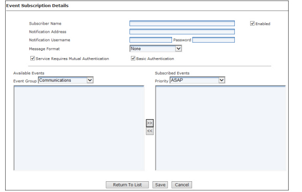
Figure 3 - 81. Event Subscription Details
2.Enter the Subscriber Name. The name must be unique to the organization.
3.Select the Enabled check box to enable the subscription.
4.Enter the Notification Address. This must be the complete url to the location of the external software.
5.Notification Username. If required, enter the user name to access the subscribing external system.
6.Password. If required, enter the password to access the subscribing external system.
7.Service Requires Mutual Authentication. If the application is using SSL, this check box must be selected.
8.Basic Authentication. Check this box if the message format is CIM 2nd Edition.
9.Available Events - Event Group.
•Select the desired Event Group from the drop down box, to populate the available events list.
•Select the events to be included in this subscription by highlighting and clicking >>.
•To remove a selected item, highlight the event and click <<
10.Subscribe Events - Priority. Select the desired Event Priority from the drop-down box.
11.Click the Save button.
These screens display hardware firmware that is available for installation. You may also use it to import additional firmware and to delete firmware that is no longer in use.
1.Click Setup > Firmware > and select firmware type.
The Firmware window will be displayed.
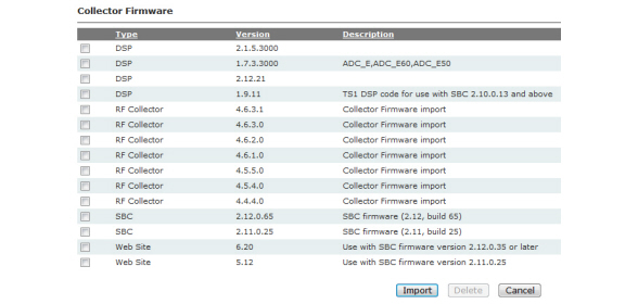
Figure 3 - 82. Collector Firmware Window
2.Click the Import button to import a new firmware package. The Import Firmware window will be displayed.

Figure 3 - 83. Import Firmware Window
3.Enter the path to the Firmware package file,
...or...
Click the Browse button to navigate to the file.
4.After locating the file, click the Import button to load the firmware into Command Center.
The firmware will be displayed in the Inventory Firmware window.
5.To remove a firmware package, select the check box(es) for any firmware package and click the Delete button.
Import Firmware/DCW .hfz files
DCW, RF endpoint firmware, meter firmware and HAN firmware are provided, as .hfz zip files, with the Command Center installation files. These files should be imported to Command Center for future use in upgrading network devices.
NOTE: Best practice is to upload all of the .hfz files on installation or upgrade of the Command Center software. The files for the firmware versions for all devices deployed in the field must be populated in Command Center.
There are several types of .hfz files, including:
•Collector Code
•Module Firmware
•DCW
•Meter Firmware
•ZigBee
Following is the procedure for uploading Endpoint firmware .hfz files:
1.Select Setup > Firmware > Communication Module.
The Communication Module Firmware window will open, shown in Figure 3 - 84, displaying a list of the endpoint firmware that are currently available in the Command Center database. When Command Center is installed for the first time this list will be empty.
NOTE: If a firmware is imported before any meter registration for a particular endpoint model has occurred, the Endpoint Model may display No Model. Once an endpoint of this model type has registered in Command Center, the Endpoint Model name will display.

Figure 3 - 84. Communication Module Firmware
2.Click Import. The Import Firmware window will open, shown in Figure 3 - 85.

Figure 3 - 85. Import Firmware
3.Firmware Package File. Enter the path to the RF endpoint firmware hfz file.
...or...
Click Browse to browse to the file location.
4.Click Import. The RF Endpoint Firmware window will open, displaying the new firmware.
NOTE: DCW, ZigBee firmware, Collector firmware, HAN firmware and Meter firmware are also imported in this manner.
Import Small DCW into Command Center. Small DCWs (Digital Control Word) are small programs which perform specific actions on the communications module.
1.Click Setup > Import Small DCW.
The Import Small DCW window will be displayed.
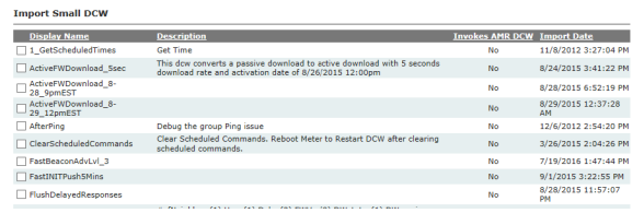
Figure 3 - 86. Import Small DCW
2.Enter the path to the Small DCW,
...or...
Use the Browse button to locate the small DCW file.
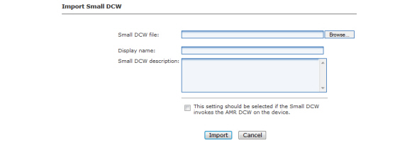
Figure 3 - 87. Import Small DCW Window
3.Enter a Display name for the small DCW.
4.Enter a Small DCW description.
5.If true, select the check-box for This setting should be selected if the Small DCW invokes the AMR DCW on the device.
6.Click the Import button.
7.To remove a Small DCW, select the check box(es) for any firmware package and click the Delete button.
The following DCW Error Response Codes are returned in Command Center:
DCWERR_INVALID_RESPONSE_LENGTH
• This code is returned when the DCW brings data, usually configuration data, back so that it can process other readings.
•LP config
•Snap read config
• It can mean several other things. Anything that prevents the DCW from receiving the amount of data that it expects can cause this error, including:
•The password is wrong.
•The meter is not responding.
•The meter is not configured for the type of data that is being requested
•The meter is busy.
•The meter has just been reprogrammed or deployed and it does not yet been running long enough to be able to process the request.
•A meter has to be running a day, at least across midnight, for a self read to be available.
•A meter has to be running at least as long as a push period for LP to work
• This code indicates that the meter has been running long enough to have captured data, i.e. the status tables are populated, but the meter does not have any data for the request.
•Self reads. The self read table is present but reports zero valid entries.
•The LP tables are present but report no active blocks.
•The LP sub-system in the meter is not active.
•This code is for LP only.
•It was added for Focus AX meters with metrology version 6.27.
•The meter reports that the number of valid intervals in the current block is greater than the maximum allowed number of intervals in a block.
•The number of valid intervals is stuck and does not increment.
DCWERR_INVALID_INTERVAL_LENGTH
• Prior to 13X DCWs, the code indicates that the LP interval length is less than five minutes.
•DCW 13.X and above indicates that the LP interval length is 0.
DCWERR_INT_REQUEST_OUT_OF_RANGE
• All the requested intervals are in the future, i.e. they don't exist in the meter yet.
•All the requested intervals are prior to the LP data in the meter.
•Usually indicates that the start time in the request is bad, but it can also happen during the first few LP pushes until the meter has accumulated enough data.
DCWERR_BLK_REQUEST_OUT_OF_RANGE
• There are not enough blocks of data to satisfy the request.
• This event is not reported by the current DCWs. The DCW will return DCWERR_NO_VALID_BLOCKS if the set is not active.
• This code is returned by an S4x when processing on demand reads of decade 20 tables, using the mapped data definition.
•The code indicates that not enough parameters were provided. The DCW expects nine bytes of parameters.
• This code is returned when a request asks for a ANSI LP set that is not available on the meter, i.e. asking for ANSI LP Set 4 on a Focus AX would return this error.
DCWERR_PASSTHROUGH_READ_FAILED
• This code is returned when a DCW tries to read data from a meter and never receives a response.